Introduction
In commercial indoor cultivation, a constant current vs constant voltage LED driver for grow lights decision isn’t just an electrical detail. It’s the component choice that decides how stable current and light output stay when line voltage drifts, temperatures rise, or a long cable run adds resistance.
That stability shows up as:
- PPFD uniformity and repeatability (fewer bays that run “hot” or “soft”)
- Uptime (fewer nuisance trips and fewer cascading failures)
- Total cost of ownership (TCO) (copper, labor, replacement cycles, and avoidable crop variability)
At a high level, LED drivers fall into two control behaviors:
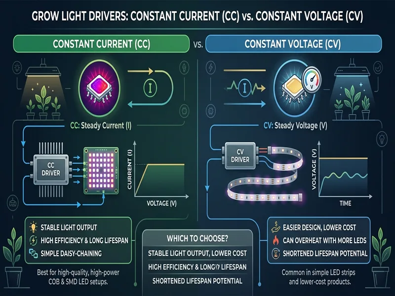
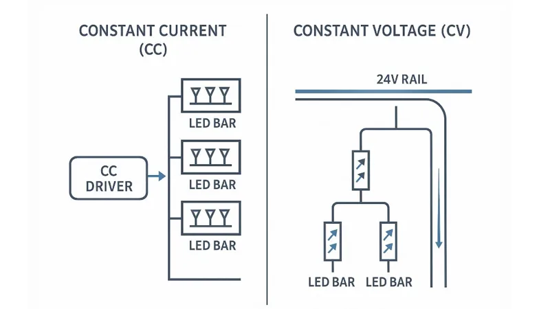
- Constant current (CC): regulates current directly; voltage moves within a rated range to maintain that current.
- Constant voltage (CV): regulates voltage (often 24V or 48V); current is determined by what the load demands.
This guide is written for operations teams specifying fixtures across rooms and sites. The goal is simple: understand where CC makes your PPFD more predictable, where CV can simplify modular builds, and which spec checks prevent the most expensive mistakes.
Table of Contents
Electrical Fundamentals (Constant Current vs Constant Voltage Driver for Grow Lights)
How Constant Current Works (Horticultural LED Driver Constant Current)
A constant-current driver is built around one job: deliver a defined output current (for example, a fixed mA value) while automatically adjusting output voltage as the LED load’s forward voltage changes.
Why that matters: LEDs are current-driven devices—small voltage differences can create large current changes. CC control gives you a clean, spec-able lever to keep light output stable even as LED junction temperature changes over time.
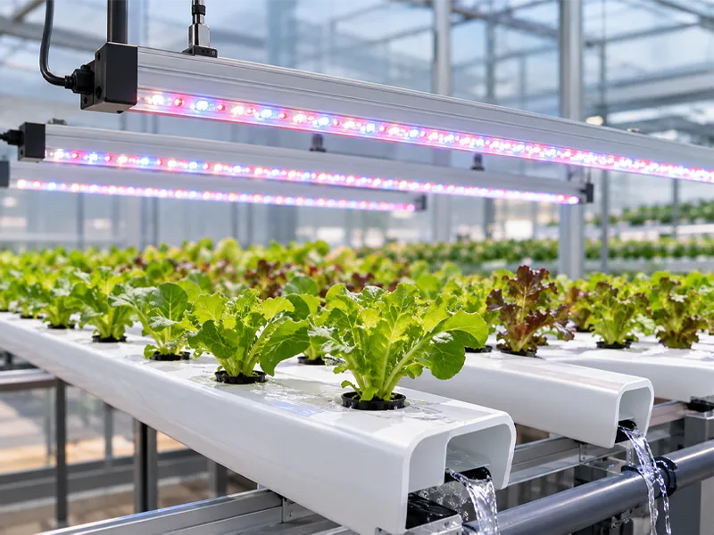
In high-power horticultural fixtures, CC is commonly paired with series or series-parallel LED bar architectures. If your bars are designed to take the same current, CC is the natural match.
For a clear overview of the behavioral difference, LEDSupply’s explainer on constant-current vs constant-voltage LED drivers is a good baseline reference.
How Constant Voltage Works
A constant-voltage driver holds its output at a target voltage—most often 24VDC in modular strip/rack builds. In practice, 24V constant voltage grow light wiring is a power-distribution problem: the driver delivers a fixed rail, and each module draws the current it needs.
This architecture can be excellent when:
- Your “load” is a standardized module designed for 24V rails.
- You want to add/remove modules without reconfiguring a current-regulated string,
- you’re distributing DC power across a rack and branching to many smaller strips.
The tradeoff is that current sharing is not automatic in parallel branches. Unless each branch has its own current regulation (or balancing method), small differences in forward voltage and temperature can translate into uneven current—and uneven light output.
Series vs Parallel Implications
Your wiring topology is where CC vs CV stops being theoretical.
Series (typical with CC):
- The same current flows through every LED/bar in the string.
- Uniformity is “built in” electrically—if the driver current is stable, string light output tends to track together.
- A single open failure can take down the whole string unless the design includes bypass strategies.
Parallel branches (common with CV rails):
- Every branch sees the same rail voltage, but the branch current can drift.
- A branch that runs hotter can pull more current (forward voltage shifts), which can increase heat further.
- Long DC rails add resistance; the far end can see lower voltage under load.
If you want a quick refresher on topology behavior, LEDSupply’s series vs parallel LED wiring guide and Avnet/Abacus’s engineering overview of LED driver selection considerations help anchor the fundamentals.
Impact on Grow Outcomes
PPFD Uniformity and Consistency
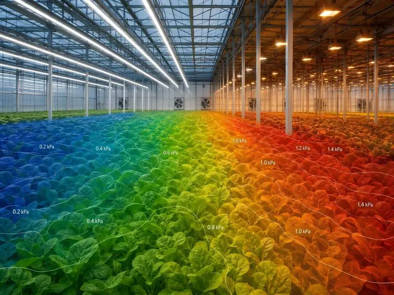
Uniformity problems in the canopy often get blamed on layout, mounting height, or optics. In multi-bar and multi-fixture systems, electrical distribution can be the hidden variable.
- In CC series or series-parallel designs, each bar (or each regulated string) is constrained by the same current target. That reduces one major source of drift: branch-to-branch current variation.
- In CV rail systems, uniformity is largely a system-design responsibility. If branches are not individually regulated, current can “walk” over time due to temperature differences and component tolerances. On a long rail, voltage drop compounds this—modules at the end can run dimmer.
The practical takeaway for growers: if you are standardizing across rooms and want to minimize troubleshooting time, CC architectures often make “same settings, same PPFD” easier to achieve.
Thermal Stability and Lifetime
Driver choice affects thermal stability in two ways:
- How hard LEDs are pushed electrically under changing conditions.
- CC limits current by design, which helps prevent overdrive when conditions change.
- CV systems depend on the downstream design (modules, resistors, or regulators) to prevent overcurrent.
- Where heat is created.
- If a CV system relies on resistive balancing to control branch current, that balancing can add heat in places you may not want it (especially in dense vertical racks).
Either architecture can be reliable when engineered correctly. The failure mode to watch is uncontrolled current increase in a subset of branches, which can accelerate depreciation and create “mystery” non-uniformity months into a rollout.
Cable Runs and Voltage Drop
This is where facility-scale deployments make the CC vs CV decision feel real.
- In a CV 24V distribution, voltage drop along a long run reduces the voltage available to downstream modules under load. If a module is voltage-sensitive (many are), output falls, and PPFD drifts bay-to-bay. Mitigations are straightforward but not free: thicker copper, shorter runs, more injection points, or moving drivers closer.
- In CC architectures, the driver adjusts voltage (within its rated window) to maintain current in the regulated string. That can reduce sensitivity to moderate line loss—up to the point where the driver hits its maximum output voltage.
Pro tip: When comparing bids, ask vendors to show the worst-case voltage at end-of-run for CV rails at full load, and the maximum driver compliance voltage headroom for CC strings at operating temperature.
Dimming and Controls
0–10V, PWM, and DALI-2
Commercial grows often inherit controls constraints: legacy 0–10V zones, new room-level automation, or site-wide BMS integration. Driver selection should follow the control reality, not the other way around.
- 0–10V is common because it’s simple and broadly compatible. It’s effective for zone dimming, but the low-end behavior depends heavily on driver design.
- PWM dimming modulates duty cycle. Done well (with sufficiently high frequency), it supports deep dimming while maintaining stable perceived output.
- DALI-2 brings addressability and richer control (groups/scenes/status), which is useful when you want per-fixture configuration and easier diagnostics at scale.
If you’re documenting control requirements for procurement, write them explicitly as LED driver dimming 0-10V PWM DALI-2 interface checks (not just “dimmable”).
If you want a controls-oriented view of how dimming methods influence stability, Acuity/eldoLED’s discussion of flicker-safe dimming methods (CCR vs PWM) is a solid starting point.
For the facility automation context in horticulture, SLTMAKS also outlines common control approaches in its guide to automated dimming systems.
Flicker, Ripple, and Dim-to-low
LEDs respond instantly. That’s good for controllability—but it means any driver ripple or low-frequency modulation can show up as visible flicker, stroboscopic effects, or camera artifacts.
At a practical level, the highest-risk conditions tend to be:
- Deep dimming (where some drivers transition control modes).
- Incompatible dimmers/controllers.
- Poorly specified minimum dim level (the fixture “falls off a cliff” below a certain setpoint).
In spec language, look for:
- Stated dimming range (not just “dimmable”).
- Stated flicker performance or referenced guidance.
- Documented behavior at dim-to-low (smooth curve, no pop-on/pop-off).
Spectrum Stability While Dimming
For single-channel white fixtures, dimming changes intensity primarily. But in some horticultural designs (especially multi-channel or mixed-diode systems), dimming can shift operating points and temperature—both of which can slightly influence output.
What to verify in a commercial rollout:
- Whether the fixture maintains the intended spectral balance across the dimming range.
- Whether control channels are truly independent (if applicable).
- Whether driver thermal limits cause an automatic step-down that looks like “mysterious” schedule drift.
Compliance and Safety
UL/ETL and UL 8800 Scope
For US commercial installs, the question isn’t “UL or ETL?”—it’s whether the equipment is listed by an OSHA-recognized NRTL to the applicable standard, with documentation you can hand to an inspector.
For horticultural luminaires, UL has published a dedicated safety standard: UL 8800 Horticultural Lighting Equipment (brief). In spec language, this is often referenced as UL 8800 horticultural luminaire compliance support: documentation and safety scope aligned to horticultural environments.
Use this as a reference point when you’re aligning fixture documentation, environmental ratings, and installation conditions.
⚠️ Warning: Don’t let procurement stop at “has a sticker.” Ask for the listing file details, the exact model/revision covered, and any conditions of acceptability that affect how drivers can be mounted or serviced.
For a procurement-friendly overview of certification expectations, SLTMAKS summarizes common checks in its buyer guide and recommended LED grow light guide.
IP65–IP67 and Wet Locations
Grow rooms aren’t gentle environments. Condensation, washdowns, and aerosols are normal. IP ratings are one of the few shorthand indicators you can use to screen environmental fit:
- IP65: dust-tight; protected against water jets
- IP67: dust-tight; protected against temporary immersion
The practical spec move is to confirm the rating for the full assembly (fixture + driver enclosure + connectors), and confirm the installation method doesn’t void it (for example: cable glands, connector mating, and mounting orientation).
Protections: OVP, OCP, SCP, OTP
Protection features aren’t marketing bullet points—they’re part of your uptime plan.
At a minimum, confirm the driver’s behavior for:
- OVP (over-voltage protection): What happens if the load disconnects or a fault causes a voltage rise?
- OCP (over-current protection): Does it clamp current, hiccup, latch-off, or fold back?
- SCP (short-circuit protection): What happens under a downstream short, and how does recovery work?
- OTP (over-temperature protection): Does it reduce output gracefully, or shut down hard—and at what case temperature?
In multi-site deployments, the most valuable detail is consistency: protection behavior should be predictable and documented so your maintenance SOPs don’t become guesswork.
Selection and ROI
When to Choose CC vs CV
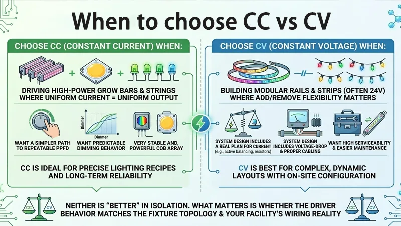
Use this as a first-pass decision logic:
- Choose CC when you’re driving high-power bars/strings where uniform current = uniform output, and you want a simpler path to repeatable PPFD and predictable dimming behavior.
- Choose CV (often 24V) when you’re building modular rails/strips where add/remove flexibility matters, and the system design includes a real plan for current balancing, voltage-drop control, and serviceability.
Neither is “better” in isolation. What matters is whether the driver behavior matches the fixture topology and your facility’s wiring reality.
Modeling TCO and Payback
Driver choice affects TCO in places that don’t show up on the fixture datasheet:
- Copper and labor: CV rails often need heavier copper, more injection points, or more localized power distribution to hold voltage at the far end.
- Downtime cost: a nuisance trip during peak operations can cost far more than the delta between driver architectures.
- Standardization and spares: fewer driver SKUs and consistent control interfaces reduce stocking complexity.
- Depreciation risk: if uneven branch current causes early drift, you may spend time re-mapping PPFD or replacing modules sooner.
A clean way to model this is to separate cost into (1) electrical distribution, (2) controls integration, (3) maintenance and spares, and (4) risk-adjusted downtime. Then compare architectures under your worst-case temperature and end-of-run assumptions.
Spec Checks and Interoperability
Before you approve a CC or CV design for multi-site rollouts, sanity-check these items:
- Output type and range: CC current range and compliance voltage; CV rail voltage and max current
- Dimming interface: 0–10V, PWM, and/or DALI-2; minimum dim level; behavior at dim-to-low
- Environmental rating: IP level and connector system rating
- Protection behavior: OVP/OCP/SCP/OTP definitions and recovery mode
- Documentation: listing details (UL/ETL), model revision traceability, installation conditions
Neutral brand example (≤30 words): SLTMAKS documentation packages commonly pair compliant, spectrum-stable multi-bar fixtures with dimming-ready drivers to simplify multi-site interoperability.
For documentation and change-control context, SLTMAKS also describes traceability expectations in its commercial grow light PCB assembly guide and broader procurement framing in the LED grow light supply chain overview.
Deployment Examples
Multi-bar array (≥600W)
Typical goal: highest uniformity with straightforward commissioning.
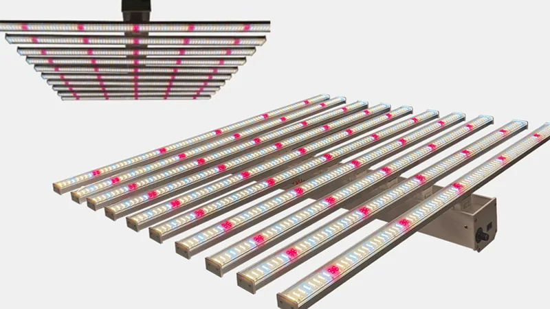
A common approach is a multi-bar fixture where LEDs are organized into current-controlled strings (series or series-parallel), fed by a CC driver (or multiple CC channels) designed around the bars’ forward-voltage window.
Operational wins:
- easier to keep bars tracking together over temperature
- clearer fault isolation (string/channel level)
- predictable dimming curves in many commercial control stacks
Watch-outs:
- confirm compliance-voltage headroom at operating temperature
- confirm what happens under a partial-string open fault
Modular Strip Racks (24V)
Typical goal: flexibility and serviceability across dense racks.
CV 24V distribution can be practical when your rack architecture is modular, and you want to swap or add strips quickly.
Operational wins:
- easier module replacement without re-stringing LEDs
- standardized 24V components can simplify spares
Watch-outs:
- manage voltage drop (run lengths, injection points, copper sizing)
- verify branch current balancing strategy and thermal behavior
- validate dimming at low output so the rack doesn’t “flicker zone-by-zone”
Retrofit from HPS to LED
Typical goal: stable yields and predictable payback without surprises.
Retrofits often inherit electrical constraints (panel capacity, conduit paths, control wiring). Your driver decision should be made with those constraints on the table.
Practical steps:
- If controls are legacy 0–10V zones, confirm the driver’s low-end behavior before committing.
- If you need long runs, model voltage drop for CV rails, or confirm CC compliance-voltage margin.
- Include protection behavior in the commissioning plan so nuisance trips don’t look like “fixture failures.”
Conclusion
Constant-current vs constant-voltage is less about electrical ideology and more about risk management in a real facility:
- CC tends to make output consistency easier when you’re driving high-power bars/strings and standardizing across rooms.
- CV can make modular builds cleaner, but you have to engineer current sharing and voltage drop so your PPFD doesn’t drift over distance and time.
Next steps that reduce rollout risk:
- Build a one-page verification checklist (driver output range, dimming interface, minimum dim, IP rating, protections, listing details).
- Run a pilot bay with worst-case cable length and temperature, then re-measure PPFD uniformity after warm-up.
- Lock the spec (including driver behavior and documentation requirements) before scaling to the next site.
FAQ
Constant current vs constant voltage LED driver: which is better for grow lights?
Neither is “better” by default. CC is usually best for high-power LED bars/strings where matching current improves uniformity. CV (often 24V/48V) is often best for modular strips/rails—if you manage branch current and voltage drop.
What is the compliance voltage on a constant-current LED driver?
It’s the output voltage range the driver can provide while still holding the rated current. Your LED string’s total forward voltage (at operating temperature) must stay within that window, with headroom.
How do I choose between a 24V and 48V constant-voltage system?
For the same power, higher voltage means lower current, which can reduce cable losses and conductor size. Choose the rail voltage your modules and safety approach support, then validate end-of-run voltage under full load.
What dimming should I specify: 0–10V, PWM, or DALI-2?
0–10V: simple, common for zone dimming.
PWM: good for deep dimming if the driver/controller pairing is compatible.
DALI-2: best for addressable fixtures, grouping/scenes, and diagnostics at scale.
What driver protections matter most in commercial grow facilities?
Prioritize OVP/OCP/SCP/OTP with clear, documented recovery behavior. Predictable protection responses reduce nuisance trips and make maintenance troubleshooting faster across multiple rooms/sites.