If you are specifying aluminum extrusion grow lights, three requirements are pulling against each other: a junction temperature ceiling set by the diode, a height and weight envelope set by the rack, and a tooling budget set by procurement. Squeeze any one of them and the other two move.
This guide is for the people who have to reconcile them — the Head of Cultivation who owns canopy conditions, the Operations Director who owns uptime and OpEx, and the Facilities Engineer who owns the electrical and thermal envelope. It assumes you have already decided to run LEDs. The question on the table is narrower and harder: what should the extrusion profile be, and how do you prove it before you commit to a die.
What follows treats thermal dynamics as a design-input generator rather than a physics lecture. Each mechanism is used only to derive a number you can put on a drawing: a junction temperature ceiling, a ΔT budget, a fin pitch, a wall thickness, a tolerance. If you want the underlying heat-transfer mechanisms developed in full — conduction through the internal thermal path, buoyancy-driven convection, and radiant emission from the sink surface — that material lives in our companion piece on passive grow light heat dissipation.
Grow light thermal management drives yield, uptime, and ROI through three levers that procurement rarely models together. It sets whether your diodes still deliver rated photon output in year five or drift out of specification in year two. It sets whether the fixture is a sealed, zero-moving-part assembly or one that depends on a fan surviving an 80% relative humidity room. And it sets how much sensible heat your HVAC has to remove, which turns a modest fixture choice into a multi-year electricity line item.
Use this as a specification checklist. Work through the performance targets first, translate them into geometry, confirm the mechanical and compliance envelope, then compare manufacturing routes against your volume. The final section lists what to lock before you issue the PO.
Table of Contents
Performance Targets that Matter
Three numbers govern everything downstream. Get them wrong, and no amount of fin optimisation rescues the design.
Junction Temperature and ΔT to Ambient
Junction temperature (Tj) is the temperature of the LED die itself, and it is the single strongest predictor of how a fixture behaves over its service life. For the mid-power white diodes used in most commercial horticultural fixtures, 85 °C is the reference point against which lifetime and maintenance specifications are published. That is a test condition, not a target. Designing to land at 85 °C leaves no headroom for a hot week, a blocked rack, or a filter that never got cleaned.
Published sensitivity data for LM301H-class diodes puts efficiency loss at roughly 0.3% per °C above 25 °C Tj, with the penalty steepening as the die approaches 65–85 °C. Industry summaries commonly report that each additional 10 °C above 85 °C can cut service life by 30–40%. Treat that figure as directional rather than a design constant, but the direction is unambiguous: every degree you remove from Tj buys back both photons and years.
ΔT to ambient is the temperature rise the fixture must overcome to hold that ceiling. In a grow room running 26–29 °C (79–84 °F), a fixture whose sink sits 45 °C above ambient is going to push die temperatures somewhere uncomfortable. The practical specification is a ΔT budget at your worst-case ambient, not at the 25 °C lab condition on the datasheet. Ask for it explicitly.
Pro Tip: Specify Tj at maximum ambient plus a margin — for example, “Tj ≤ 75 °C at Ta = 35 °C” — rather than specifying a sink temperature. A sink temperature is easy to pass on a bench and hard to hold in a rack. A junction-temperature requirement forces the supplier to publish the full thermal resistance path.
PPFD Stability and PPE Over Time
Photon output decays. The question is how fast, and the answer is largely thermal.
Maintenance is expressed as L90 or Q90 — the running hours at which a fixture retains 90% of its initial output. For LM301B/LM301H-class diodes, the commonly cited band sits between L90 at 36,000 and 54,000 hours, depending on drive current and thermal design. Quality commercial fixtures lose 5–10% of initial output over the first 25,000 hours, while budget fixtures with poorer thermal paths lose 20–30% over the same window. Same diode families, but a different extruded aluminum heat sink, grow light design, and a materially different five-year photon budget.
That delta is not abstract. If you commissioned a room to deliver a specific daily light integral and the fixtures decay ahead of plan, you either accept lower yield or extend photoperiod and pay for the extra energy. Both outcomes trace back to a profile decision made eighteen months earlier.
The practical specification: require a published photon-flux-maintenance figure at a stated Tj, and require the manufacturer to state the drive current at which it was measured. A maintenance number without a temperature and a current is not a specification. Photometric planning against those decayed values belongs in your commercial grow light layout and heat load model, not in a spreadsheet assembled after delivery.
Fin Area per Watt and Allowable Thermal Resistance
This is where thermal design becomes arithmetic, and where suppliers diverge most.
Natural convection in air delivers a heat-transfer coefficient of roughly 5–25 W/m²·K. Forced air can reach ten times that. Because passive grow-light fixtures deliberately reject fans, surface area and ΔT must carry the entire convective load — which is why passive sinks are physically larger than their fan-cooled equivalents for the same wattage.
Published rules of thumb for finned surface area span a wide range, and the width of that range is informative:
| Application | Fin surface area per watt of thermal load |
|---|---|
| Minimum for a well-ventilated sink | ~3 in²/W (≈19 cm²/W) |
| Commonly cited for natural convection | ~10 in²/W (≈65 cm²/W) |
| Conservative passive design | ~17 in²/W (≈110 cm²/W) |
A 500 W fixture dissipating 250 W as heat is therefore a 780–1,400 cm² surface-area problem at the low end and a 2,750 cm² problem at the conservative end. That gap separates an extrusion you can run on an existing die from one that needs a custom 200 mm-wide aluminum extrusion heat sink profile.
Allowable thermal resistance is the output of that arithmetic. Passive extruded sinks typically land in the 1–5 °C/W range for sink-to-ambient resistance, with carefully designed high-power assemblies reaching 0.25–1.5 °C/W. The required value comes from your own targets: subtract the junction-to-case and interface resistances from the total budget, and what remains is what the extrusion has to deliver. Suppliers who cannot produce that number should not be quoting the job.
Thermal Geometry and Materials
Once you know the required sink-to-ambient resistance, LED grow light extrusion profile design becomes a geometry problem with a manufacturability fence around it.
6063-T5/T6 and Base Thickness Choices
Alloy choice is settled quickly because the trade-off is narrow. 6063-T5 is the default for extruded heat sinks, with thermal conductivity around 200–209 W/m·K measured at room temperature. Its value lies less in the peak number than in extrudability: 6063 accepts high fin density and complex fin geometry without tearing, which is exactly what a heat sink needs.
6061-T6 is stronger and machines better, but its thermal conductivity is around 167 W/m·K — roughly 15–20% lower. Sourcing managers sometimes request 6061 on the assumption that stronger is safer. For a heat sink, that instinct costs thermal performance for structural margin the fixture rarely needs. Use 6061 where the profile also carries structural or thread-bearing duty, not as a general default.
Temper matters less than alloy for conductivity but does affect dimensional stability through secondary machining. T6 raises yield strength at some cost to formability; for a straight extruded bar that is then sawn and drilled, the practical difference is usually small. Confirm what the supplier is actually running, because substituting temper without notice is a common and quiet change.
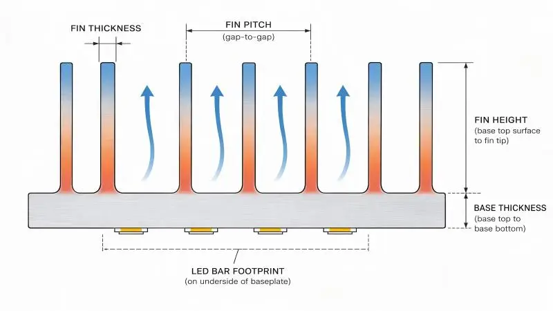
Base thickness is the least interesting variable and one of the most consequential. The baseplate spreads heat laterally from a narrow LED footprint into the full fin array. Make it too thin and you create a lateral spreading bottleneck: the fins directly above the diodes run hot while the outer fins idle. Make it too thick and you add mass, cost, and thermal lag without adding surface area. Base thickness should be sized against the LED bar footprint and the spreading distance to the outermost fin, not copied from a stock profile.
Fin spacing, Height, and Thickness Trade-Offs
Fin geometry is where thermal theory meets the die. A die produces one cross-section, repeated for the length of the billet, so every dimension here is locked at tooling. Change your mind later, and you buy a new die.
Fin spacing is governed by boundary-layer behaviour. Each fin surface carries a stagnant air film, and if adjacent films merge, the channel stops moving air and the extra surface area you paid for contributes almost nothing. Lumileds’ practical heat-sink design guidance for illumination puts the natural-convection optimum around 6–10 mm of free space between fins, with roughly 8 mm as a generic starting point.
For grow-light duty in a rack environment, published guidance for passive fixtures runs wider, at 10–15 mm. Fans change the arithmetic entirely: forced flow can push air through 2–4 mm channels, which is why fan-cooled sinks look so much denser.
The design rule that follows: size fin spacing for the airflow you actually have, not the airflow you hope for. A profile designed for 4 mm spacing will underperform passively and cannot be rescued by adding a small circulation fan later, because the fan will not develop enough static pressure to clear those channels.
Fin height buys surface area, but with sharply diminishing returns. Fin efficiency falls as height increases because the fin tip runs cooler than the base and contributes less. Tall, tightly packed fins also raise die pressure and scrap risk during extrusion.
Fin thickness sets both the conduction cross-section within the fin and the manufacturability envelope. Thinner fins conduct less heat along their length but pack more surface into the same width. The practical production range for extruded heat-sink profiles is roughly 1–3 mm, with about 0.5 mm as a lower practical limit for specialty profiles that are considerably harder to run consistently.
Combining these, the manufacturability bands look like this:
| Fin aspect ratio (height: thickness) | Practical posture | Consequence |
|---|---|---|
| 3:1 – 5:1 | Standard, repeatable | Lower die cost, predictable scrap rate, forgiving of tolerance |
| 8:1 – 15:1 | Advanced die capability required | Higher die pressure, faster die wear, tighter process control |
| Above ~15:1 | Specialty only | Scrap risk and cost rise steeply; validate with the extruder before quoting |
Two further constraints deserve a place on your drawing. Minimum wall thickness for reliable production is generally 1.0–1.5 mm; thinner walls risk tearing or incomplete die fill. And maximum profile width sits around 500 mm, beyond which press capacity and cost escalate. If your fixture needs a wider thermal footprint than the profile provides, the answer is usually multiple parallel extrusions joined by a structural rail, not one very wide die.
⚠️ Warning: Do not design a sealed, tightly finned profile and assume it will cool passively. Tight fin spacing plus an enclosure that blocks vertical airflow is the single most common cause of a passive fixture failing its heat-rise test. Trapped air between fins behaves like insulation.
Emissivity and Anodized Extruded Aluminum Heat Sinks
Convection does most of the work in a passive grow-light sink, but radiation is not negligible, and it is unusually cheap to improve.
Mill-finish aluminum is a poor radiant emitter. Its emissivity sits around 0.05–0.10, meaning it reflects most of the infrared energy it could otherwise shed. Anodizing changes this dramatically. The anodic oxide layer — typically 10–25 µm thick — is microporous and raises emissivity to roughly 0.85–0.90. A 2020 study from the SFU thermal group on naturally cooled heat sinks for power electronics measured an improvement of approximately 14.7% in overall performance after anodization.
Two implications for the drawing. First, specify the finish, not just the colour. A black anodized finish and a clear anodized finish both deliver the emissivity benefit; a painted or powder-coated finish may not, and an anodized finish applied too thinly will underperform. Second, anodize after any machining that exposes bare metal, and mask or re-seal cut edges if the profile is sawn to length after finishing — a raw sawn end is a small but real loss of radiant surface.
Because the emissivity gain is roughly 10–15% of total dissipation, anodizing will not rescue an undersized profile. It is the cheap increment you take once the geometry is already right.
Airflow and Mechanical Integration for Aluminum Extrusion Grow Lights
A profile that performs on a bench can still fail in a rack. Integration decides which of those two outcomes you get.
Orientation for Chimney Effect vs Forced Flow
Natural convection depends on buoyancy. Warm air expands, loses density, and rises, drawing cooler air in behind it. Fin arrays aligned with that vertical flow develop a chimney or stack effect that keeps air moving without any mechanical assistance. Rotate the same profile so fins run horizontally, and the effect collapses — buoyancy now pulls air across the fins rather than up through the channels, and effective heat transfer drops.
Published guidance for passive grow-light fixtures puts the penalty for blocked or inverted fin orientation at 15 °C or more of added junction temperature. That is the difference between a comfortable design margin and a warranty claim.
The integration rules that follow are straightforward but frequently violated in rack builds:
- Mount linear bars with fins vertical wherever the fixture geometry permits.
- Preserve ceiling or rack clearance of 8–12 inches (20–30 cm) above the fixture so rising air has somewhere to go.
- If the rack design forces a horizontal fixture, treat the profile as a forced-convection design and supply it with real airflow: a gentle horizontal air velocity of 0.3–0.5 m/s across the fin array is enough for small-diameter, low-speed circulation fans mounted to avoid direct canopy blast.
Forced flow is not automatically better. A fan that pushes air through fins also pushes humid, spore-laden room air, and it introduces a moving part into a wet environment. Where airflow is genuinely required, use low-speed circulation fans mounted clear of the canopy rather than small, high-speed fans integrated into the fixture.
Sealing, IP Ratings, and Cable Routing in Racks
Grow rooms combine high humidity, frequent washdown, and mineral-laden water. Enclosure strategy has to account for all three.
IP ratings describe ingress protection and nothing else. IPX6 covers protection against powerful water jets; IPX7 adds protection against temporary immersion. A washdown room commonly specifies IP66 or IP67 for the fixture enclosure. What IP ratings do not cover is the luminaire environmental rating required by safety standards — that is a separate evaluation, addressed in the compliance section below.
The practical conflict is that cooling and sealing want opposite things. Fins need to be exposed to room air to work; electronics need to be sealed away from it. The usual resolution is a hybrid architecture: seal the optical and driver side to the required IP rating, leave the fin array exposed, and manage the boundary carefully. Cable entries are the weak point. Specifying a sealed gland or potted entry rather than a grommet costs little and eliminates a common failure mode in wet rooms.
Driver placement deserves a decision of its own. Onboard drivers add roughly 5–15% of fixture wattage as heat directly inside the room — on a 1,000 W fixture, that is 50–100 W of continuous additional sensible load. Remote-mounting drivers move that heat to a location you can ventilate independently, and it simplifies the fixture-side sealed assembly considerably. For multi-tier racks where driver access is difficult, remote mounting also converts a maintenance task from “disassemble the tier” to “open the control cabinet.”
Modular Light Bars and Service Access
The advantage of extrusion as a manufacturing route is that it produces a constant cross-section for the full length of a billet. Use that property deliberately.
If fin pitch, fin thickness, and base thickness are constant along the bar, then one die serves every fixture length in your fleet. Model variants — output, spectrum, connector position — get pushed into secondary operations or into the PCBA, not into the profile. A facility standardising across sites can run a single profile and a single die, varying only the cut length and the board. That is a meaningful reduction in tooling exposure and spare-part complexity.
Design the service side at the same time. Establish where a bar can be released from the frame with the rack loaded, whether the driver is reachable without dismantling a tier, and whether the fin array can be cleaned without removing the fixture. Dust and debris accumulating between fins degrade performance over time; a cleaning schedule that requires disassembly will not be followed.
A professional supplier aligns spectrum, thermal design, and certification rather than treating them as separate quotations. In practice, that means one engineering review covering the PCBA layout and its thermal footprint, the extrusion profile that carries that footprint, and the compliance documentation ahead of tooling.
SLTMAKS structures its commercial LED grow light programmes around that sequence, including custom LED spectrum development scoped alongside the mechanical and thermal envelope rather than after it — which matters because the diode spread and drive current determine the heat load the extrusion must carry.
Manufacturing Methods Compared
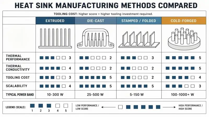
Extrusion is not the only route, and it is not always the right one. The choice turns on power density, geometry complexity, volume, and how much tooling you are prepared to fund.
Extrusion vs Die-Cast Housings
Extruded aluminum typically uses 6063-series alloy with thermal conductivity around 200–218 W/m·K. The process pushes heated alloy through a shaped die to produce a continuous profile, so tooling is a die rather than a mold, and cost is moderate. The result is consistent, dense material with predictable conductivity, at low weight (aluminum is about 2.7 g/cm³) and low-to-moderate unit cost at volume.
Die-casting uses alloys such as ADC12 or A380, whose conductivity lands around 90–96 W/m·K, with the upper practical limit for cast components generally cited around 150–160 W/m·K depending on alloy and process. The gap is not purely alloy choice — casting porosity introduces voids into the conduction path and raises thermal resistance further.
Casting’s real advantages are geometric freedom and very high-volume automation: complex housings with integrated mounting features, cable channels, and non-uniform fin layouts are straightforward in a mold and awkward or impossible in a die. Tooling cost is high, and amortisation requires volume.
The rule that follows: extrude when the thermal requirement is the constraint; cast when geometry complexity is the constraint and volume is high.
Stamped and Folded Fin Assemblies
Stamped and folded fin constructions bond thin sheet-metal fins to a baseplate. Material use is minimal, unit cost is the lowest of the four routes, and scalability for simple parts at very high volume is excellent. The cost is performance: shallow, thin features with an interface between fin and base, and a bond line that adds thermal resistance. DigiKey’s thermal design guidelines characterise stamped heat sinks plainly as inexpensive with minimal performance, against extruded sinks at moderate price and mid-level performance.
For a grow light, that places stamped assemblies in lower-power or cost-driven fixtures. There is also a service-life consideration: bonded interfaces are more sensitive to thermal cycling and to moisture exposure than a single homogeneous extrusion, and the bond line is not something you can inspect in the field.
Cold-Forged Heat Sinks for High Density
Cold forging deforms a billet into shape under high pressure, producing a dense part with fewer voids and a continuous metal path from base to fin — no bond line, no die-fill porosity. One industry comparison reports cold-forged heat sinks at roughly 13% better thermal conductivity than extruded and up to 60% better than die-cast; treat those figures as directional vendor data rather than a design guarantee, but the mechanism is credible.
The trade-offs are tooling and design freedom. Forging tooling sits above stamping and often at or above extrusion, and forged parts have less latitude for intricate hollow features than castings do. Cold forging tends to be selected for high power density — compact assemblies carrying 100 W and above in a small envelope — where per-unit cost matters less than getting the heat out of a tight volume.
Compliance, Safety, and ROI
Thermal design decisions propagate into certification scope and into the operating budget. Both need to be closed out before tooling.
UL 8800, Wet Locations, and Photobiological Safety
ANSI/CAN/UL 8800, the harmonised U.S. and Canadian standard for Horticultural Lighting Equipment and Systems, was published in 2019 and had its scope expanded in 2023 to include updated photobiological safety marking requirements. For a grow-light project, three of its requirements shape the specification.
First, a horticultural luminaire must be rated suitable for a damp location as applicable to the installation environment, per UL’s published overview of UL 8800. Grow rooms and washdown areas generally push that to a wet-location rating, and the evaluation is not satisfied by an IP claim alone — the two address different questions.
Second, UL 8800 includes ingress protection testing for dust, moisture, and water, and it evaluates suitability in elevated ambient temperatures. That elevated-ambient evaluation is where your thermal design meets your certification file: a fixture qualified at 25 °C ambient and installed in a 35 °C room is a specification mismatch, not a warranty nuance.
Third, photobiological safety is assessed in line with IEC 62471 conventions, with assigned classifications limited to Risk Group 0, 1, or 2. RG3 is not permitted for these products. For fixtures operating at high PPFD close to workers, the risk group and the associated marking requirements belong in the same review as the thermal design, because beam intensity and fixture placement both feed the assessment.
Certification to UL 8800 is also a safety requirement for a product to be added to, or remain on, the DLC horticultural Qualified Products List. The two are linked, not parallel.
DLC Horticultural QPL V4.0 Timelines and Rebates
The DesignLights Consortium’s Horticultural Technical Requirements V4.0 became effective on 18 April 2025, when applications opened. Existing products on the previous version had to be included in update applications by 31 October 2025 or face removal. Products not updated to V4.0 were scheduled for delisting on 5 January 2026. Some utility programmes began requiring V4.0 listing for incentive eligibility from 1 July 2026.
If you are procuring now, that timeline has already resolved into a practical screen: any fixture you shortlist should be listed under V4.0, and you should be able to see the listing. Our own resource on DLC-certified grow lights for commercial farms tracks the transition, and the authoritative source remains the DLC’s V4.0 horticultural technical requirements page.
Rebates are where listing status turns into money. Programmes are administered by utilities and state agencies, not by UL or by the DLC, and they commonly require three things: DLC Hort V4.0 listing, safety certification to UL 8800 or an equivalent, and written pre-approval before purchase. Some programmes also set a minimum warranty term and a minimum photon efficacy — one 2026 programme summary cites a minimum PPE of 2.5 µmol/J and a minimum five-year warranty.
Reported rebate offsets range widely, with one industry source citing 20–50% of fixture capital cost. That range is program-specific, so confirm the figure with your utility before modelling payback. The pre-approval requirement is the one that trips projects up: buy first and you can lose eligibility entirely.
Reliability, HVAC Load, and Total Cost of Ownership
Passive thermal design earns its return in two places: failure modes removed and cooling load avoided.
On reliability, the comparison is structural rather than incremental. A passive fixture has no bearing, no motor, and no fan controller to fail. Fan-cooled fixtures in high-humidity environments place a mechanical assembly in the most hostile position in the room, and a fan failure does not degrade gracefully — it removes the cooling path at once. Passive designs move the entire thermal load into a static extrusion whose failure mode is gradual dust accumulation, which maintenance can address.
On HVAC, the arithmetic is blunt. Every watt that does not leave the room as light becomes sensible heat, and the standard conversion is 1 W = 3.412 BTU/h. A 600 W fixture introduces roughly 2,047 BTU/h of load regardless of technology. Practice in grow-room design often adds a further 15–20% above the raw lighting figure to cover miscellaneous gains. Because a sealed facility must remove the full connected lighting load essentially, high-density rooms drive large HVAC capacity.
That load then multiplies through the chiller. HVAC electrical input approximates cooling output divided by coefficient of performance: at COP 4, roughly 0.25 W of electricity per watt of heat removed; at COP 2, roughly 0.5 W. So a 1,000 W fixture that generates 50–100 W of extra room heat through an onboard driver also drags a further 12–50 W of chiller input along with it — continuously, for the life of the installation. Our detailed treatment of LED grow light heat radiation and HVAC impact works through the full load calculation.
Ten-year TCO is dominated by three lines: fixture capex, lighting electricity, and HVAC electricity and capacity. The passive-versus-fan delta is real but smaller than the LED-versus-HID delta, and it is usually decided by maintenance and downtime exposure rather than by watts. The larger lever is fixture efficacy, because it reduces both the lighting bill and every downstream cooling cost simultaneously.
Conclusion
Key Design decisions to Lock before Procurement
Key Takeaway: Six items belong on the specification before the first die is cut — Tj ceiling at maximum ambient, allowable sink-to-ambient thermal resistance in °C/W, fin pitch and fin thickness with a stated aspect ratio, minimum wall thickness and governing tolerance standard, finish specification including anodizing thickness, and the enclosure environmental and IP requirements.
Each of those becomes expensive to change after tooling. A fin pitch adjustment means a new die. A base-plate thickness change means a new die. An anodizing specification change after finishing means rework or scrap. This is the point in the programme where engineering review buys the most and costs the least.
Confirm the tolerance basis explicitly. EN 755-9 governs dimensional and form tolerances for extruded profiles with a cross-section within a circumscribing circle up to 800 mm, and publishes profile-height tolerances that scale from roughly ±0.25 mm on small sections to as much as ±5.0 mm on very large ones. ASTM B221 is the corresponding U.S. product standard. In practice, tolerance expectations that matter to a heat sink — fin thickness consistency, wall uniformity, fin-to-base squareness — should be written on the drawing with reference to the standard, not left to the standard’s default class.
Industry rule-of-thumb figures for general extrusion work are approximately ±1% on linear dimensions, ±5–10% on wall thickness (with a higher percentage on thinner walls), and ±2° on angular geometry; these are useful for early sanity checks, not as a substitute for the drawing. European Aluminium’s extruded-products guidance is a reasonable reference point when framing those numbers in a specification.
How to Validate with Prototypes, IES/TM-21, and Heat-Rise Tests
Specification gets you to a die. Verification gets you to a purchase order.
The sequence that catches problems while they are still cheap:
- Manufacturability review with the extruder, before tooling. Provide the thermal requirement, the envelope, and the target airflow direction. Ask directly whether the fin aspect ratio sits in a repeatable band or a specialty band, and ask what scrap rate they consider normal for that geometry. A supplier who will not answer that question is telling you something.
- Die sample and section verification. Measure fin thickness, fin pitch, wall thickness, and base thickness across the cross-section, not just at one point. Verify the alloy and temper against the drawing. Confirm anodizing thickness on a finished sample.
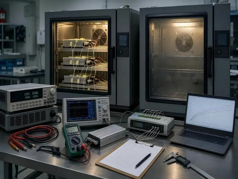
- Heat-rise test at worst-case conditions. Run the assembly at maximum rated drive current in the maximum ambient you expect, at the mounting orientation used in the facility, and record junction temperature from the diode manufacturer’s correlation or a validated thermal model. This is the test that catches orientation, clearance, and sealing errors before they reach a rack.
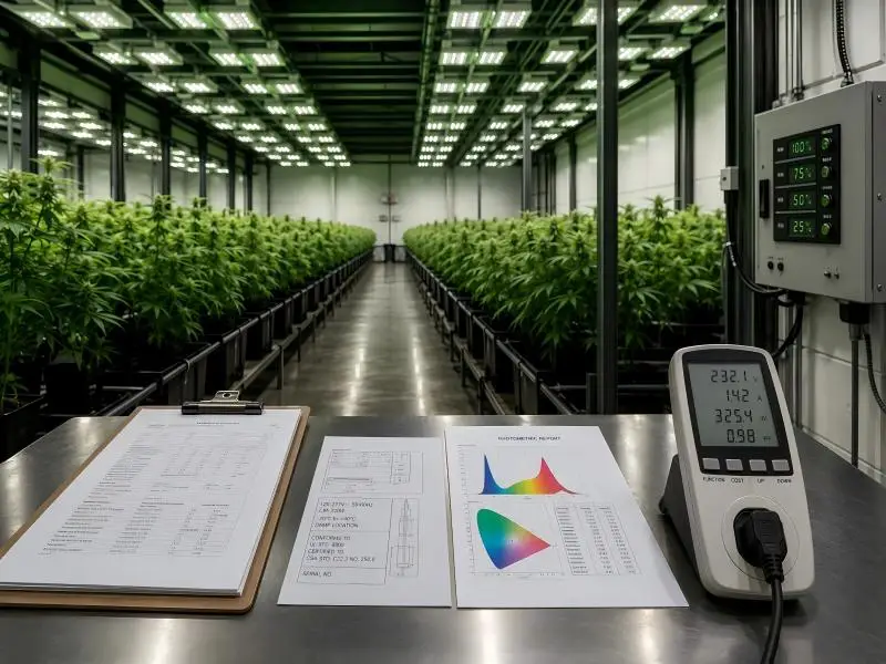
- Photometric validation. Obtain the full IES file and the TM-21 style maintenance projection, and check that the maintenance figure is stated at a Tj you actually achieve in service rather than at a bench condition.
- Compliance documentation review. Confirm the UL 8800 environmental rating for the specific configuration, the IEC 62471 risk group, and the DLC QPL listing identifier for the exact model and wattage being procured. Configurations can differ in listing status.
Next Steps to Model ROI and Standardize Across Sites
For the ROI model, use four inputs: purchase price including tooling amortisation, lighting kWh at your utility rate, HVAC kWh calculated from connected load at your chiller COP, and maintenance and downtime cost per intervention. Run it against two or three candidate profiles rather than one — the comparison is what surfaces whether a lower-cost geometry is genuinely cheaper over the life of the room.
Standardisation is the other lever, and it compounds. A profile that is constant along its length lets a multi-site operator run one die across every fixture length, keeps spares interchangeable between sites, and reduces the engineering review to a single pass rather than one per location. If you are scheduling a rollout across multiple facilities, the specification work done once is amortised across all of them.
If you want that review done against your actual facility parameters — ambient profile, rack geometry, target PPFD, and the compliance envelope for your jurisdiction — that is the conversation worth having before tooling is committed.
FAQ
Which aluminum alloy is best for extruded grow light heat sinks?
Which aluminum alloy is best for extruded grow light heat sinks?
6063-T5 is the standard choice. Its thermal conductivity sits around 200–209 W/m·K at room temperature, and it extrudes cleanly into dense, complex fin geometries without tearing — the exact property a heat sink needs. 6061-T6 is stronger but conducts at roughly 167 W/m·K, about 15–20% lower, so it belongs only where the profile also carries structural or thread-bearing duty. If someone quotes 6061 as a “safer” default for a pure thermal part, that is a performance trade you did not ask for.
What fin spacing does a passive grow light need?
What fin spacing does a passive grow light need?
For natural convection, the practical band is 6–10 mm of free space between fins, with roughly 8 mm as a sensible starting point. Passive fixtures sitting in rack environments often run wider, at 10–15 mm. The reason is boundary layers: each fin carries a stagnant air film, and when adjacent films merge, the channel stops moving air, and the extra surface area contributes almost nothing. Tightly packed fins of 2–4 mm only work under forced flow, so never specify them for a fanless fixture on the assumption you can add a small circulation fan later.
How hot can an LED grow light run before lifespan drops?
How hot can an LED grow light run before lifespan drops?
The reference point for mid-power white diodes is 85 °C junction temperature (Tj) — but that is a test condition, not a design target. LM301H-class data puts efficiency loss at roughly 0.3% per °C above 25 °C Tj, and industry summaries report that each additional 10 °C above 85 °C can cut service life by 30–40%. Specify ceiling values at your worst-case ambient instead, for example, “Tj ≤ 75 °C at Ta = 35 °C.” As a rule of thumb, keep Tj below 65 °C and fixtures can credibly hold their 50,000-hour rating.