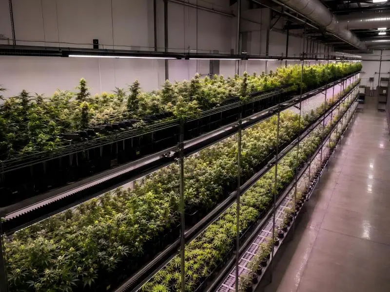
Commercial indoor farming relies on light-emitting diodes (LEDs) to deliver precise photon flux densities across targeted photosynthetic spectrums. Yet a persistent physical reality remains: even the highest-efficacy horticultural LEDs convert roughly 45% to 55% of their electrical power into thermal energy rather than photosynthetically active radiation (PAR).
Unlike legacy High-Pressure Sodium (HPS) fixtures that project intense radiant infrared heat downward onto plant leaves, LEDs generate heat internally at the microscopic semiconductor die. If this thermal energy accumulates at the diode junction, performance degrades rapidly. Diode junction temperatures exceeding manufacturer limits trigger accelerated phosphor breakdown, spectral drift, photon-efficacy decay (mumol/J loss), and eventual fixture failure.
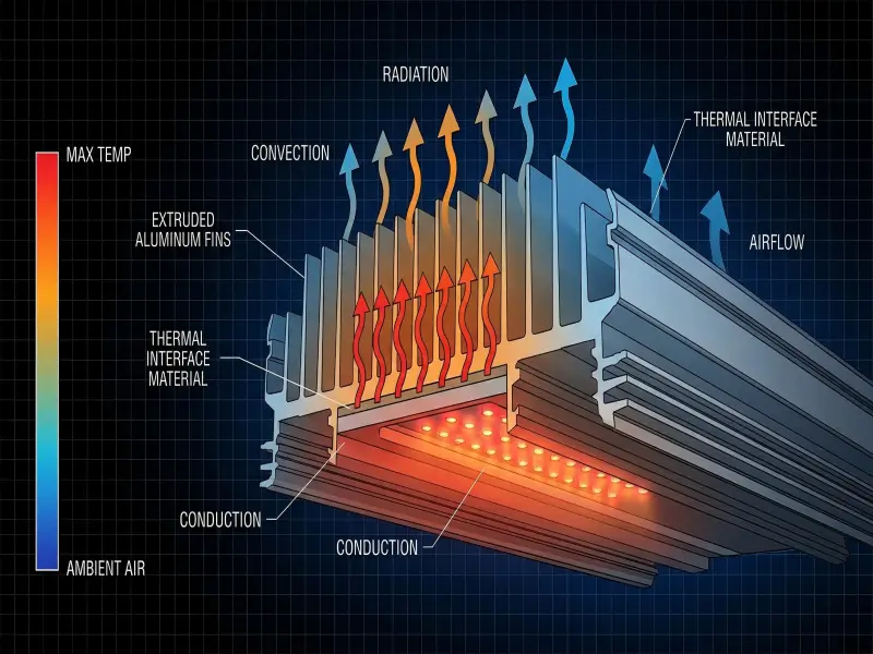
To eliminate mechanical failure points in humid cultivation environments, modern commercial fixtures rely on passive cooling. Passive thermal management uses no fans or moving parts. The methods for Heat Dissipation in Passive Grow Lights do not utilize fans or moving parts; instead, they rely on a continuous thermal chain governed by the three primary modes of heat transfer: conduction, convection, and radiation.
Understanding how these physical mechanisms interact allows facility managers, head cultivators, and lighting engineers to evaluate fixture reliability, protect canopy microclimates, and optimize HVAC operational costs
Table of Contents
Why Thermal Management Defines Diode Lifespan and Photon Efficacy
The semiconductor junction of an LED is microscopic, typically measuring less than one square millimeter. When electrical current passes through the diode, photon emission occurs alongside thermal dissipation. Because LEDs do not radiate heat forward in their light beam, thermal energy must travel backward through the fixture housing.
Thermal stress acts as the primary driver of LED lumen depreciation. The operational lifespan of a fixture is measured by its L70 or L90 threshold—the point at which photon output degrades to 70% or 90% of its initial rating.
When diode junction temperatures (Tj) remain below 85°C, high-grade diodes can operate for over 50,000 hours with minimal decay. However, for every 10°C rise in junction temperature above design limits, the rate of semiconductor degradation doubles.
Key Takeaway: High ambient temperatures do not just make a grow room warm—they alter the internal crystal lattice of LED diodes. Uncontrolled junction heat shifts red and far-red emission wavelengths, reduces overall photon flux, and shortens fixture operating lifespan.
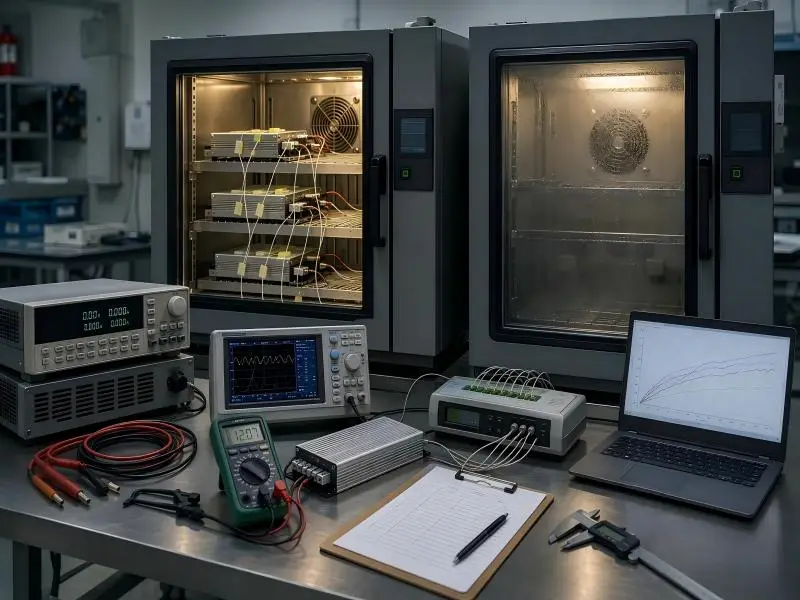
To determine whether a passive fixture can maintain safe operating temperatures under real-world facility conditions, thermal engineers calculate the total thermal resistance (RθTotal) across the entire path from the diode die to the surrounding room air:
Tj = Ta + Pd × (RθJC + RθTIM + RθSA)
Where:
- Tj = Diode Junction Temperature (°C)
- Ta = Ambient Temperature surrounding the fixture (°C)
- Pd = Thermal Power Dissipated (Watts)
- RθJC= Junction-to-Case Thermal Resistance
- RθTIM = Thermal Interface Material Resistance
- RθSA = Heat Sink-to-Ambient Thermal Resistance
As documented in TPS Elektronik’s thermal resistance guide, controlling each component of this thermal resistance chain is necessary to keep junction temperatures within safe operating limits under natural convection.
Mechanism 1 — Conduction: Moving Heat Away From the Semiconductor Die
Conduction is the direct transfer of thermal energy through solid matter via molecular vibration and electron transport. In a passively cooled LED grow light, conduction forms the internal thermal highway. Its job is to draw heat away from the semiconductor die as quickly as it is generated.
The rate of conductive heat transfer is governed by Fourier’s Law of Thermal Conduction:
q = -k · A · (dT/dx)
Where:
- q = Heat transfer rate (Watts)
- k = Thermal conductivity of the material (W/(m·K))
- A = Cross-sectional surface area perpendicular to heat flow (m2)
- dT/dx = Temperature gradient across the thickness (K/m)
To maximize conductive heat transfer (q), engineers must select materials with high thermal conductivity (k) and eliminate microscopic air gaps across material interfaces.
The Internal Thermal Path
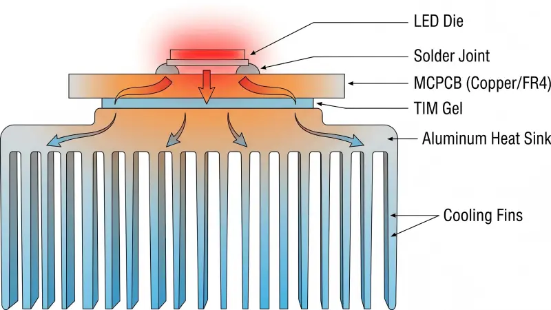
- Diode to solder pad: Heat flows from the semiconductor junction through the lead frame to the gold or tin-silver-copper solder joint.
- Metal-Core Printed Circuit Board (MCPCB): The solder pads rest on an MCPCB consisting of a copper circuit layer, a thin dielectric insulation layer, and an aluminum base plate. High-grade horticultural fixtures utilize dielectric layers rated at2.0 W/m·K to 3.0 W/m·K to prevent thermal choking at the PCB level.
- Thermal Interface Material (TIM): The metal surface of an MCPCB and the surface of a heat sink baseplate appear smooth to the naked eye, but microscopic inspection reveals air pits. Air is an exceptionally poor conductor (k_air ≈ 0.026 W/(m·K)). Applying high-performance phase-change TIM or silicone thermal grease (k ≈ 3.0–6.0 W/m·K) fills these voids and drops interface thermal resistance by up to 80%.
- Heat sink baseplate: Thermal energy enters the solid aluminum base, spreading laterally before migrating into the vertical cooling fins.
Material Selection: Extruded 6063-T5 vs. Die-Cast Aluminum
The choice of aluminum alloy dictates how efficiently heat spreads through the heat sink body:
| Material Alloy | Thermal Conductivity (k) | Manufacturing Process | Performance Impact in Grow Lights |
| Extruded aluminum (6063-T5) | 200–209 W/m·K | High-pressure hydraulic extrusion through precision steel dies | Superior: High structural purity, zero internal air pockets, maximum conductive heat spreading. |
| Cast aluminum (ADC12 / A380) | 96–100 W/m·K | Molten metal poured into mold cavities | Inferior: High silicon content reduces conductivity by half; micro-porosity traps heat inside baseplate. |
| Stamped sheet Metal | 120–160 W/m·K | Bending thin aluminum sheets | Poor: Insufficient base mass to spread heat laterally across high-power bar light arrays. |
Passively cooled fixtures specified for multi-tier commercial racks depend on 6063-T5 extruded aluminum bars. The high thermal conductivity ensures that heat generated beneath dense diode clusters spreads evenly across the entire length of the fixture without creating localized hot spots.
Mechanism 2 — Convection: Dissipating Thermal Energy into Ambient Air
Once conductive transfer brings heat to the outer surface of the aluminum heat sink, thermal management shifts to convection. Convection is the transfer of heat from a solid surface into a moving fluid—in this case, the ambient air of the grow room.
Convective heat transfer follows Newton’s Law of Cooling:
q = h · A · (Ts – T∞)
Where:
- h = Convective heat transfer coefficient (W/m²·K)
- A = Total exposed surface area of the heat sink fins (m²)
- Ts = Heat sink surface temperature (°C)
- T∞ = Ambient air temperature surrounding the fixture (°C)
In a passive system, there are no mechanical fans forcing air movement (h_forced). Instead, cooling relies entirely on natural convection driven by thermal buoyancy.
The Buoyancy-Driven Stack Effect
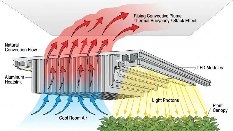
When air comes into direct contact with warm aluminum cooling fins, heat transfers into the air layer. As air heats up, it expands, becomes less dense than the cooler surrounding air, and rises upward. This movement creates a localized low-pressure zone beneath the fixture, pulling cooler room air upward into the fin array from below.
This continuous upward motion—known as the stack effect or natural convective plume—draws thermal energy away from the fixture without requiring mechanical energy.
Fin Architecture and Airflow Choking
Designing heat sinks for natural convection requires a different fin geometry than designing for active fan-cooled systems:
- Fin spacing (Pitch): Fan-forced systems use tightly packed fins spaced 2 mm to 4 mm apart because pressurized air can force its way through narrow channels. In passive systems, tightly packed fins create boundary-layer resistance that chokes natural air movement. Passive aluminum heat sinks require wider fin spacing—typically 10 mm to 15 mm—allowing buoyant air currents to flow freely between fins.
- Fin height and orientation: Vertical fin orientation aligns with natural buoyancy. Horizontal cross-fins or flat plates block rising air plumes, raising convective thermal resistance (RθSA).
Pro tip: Always install passive LED bar lights with cooling fins oriented vertically relative to air movement. Mounting bars upside down or blocking fin channels with cabling restricts natural convective air plumes and can increase diode junction temperatures by 15°C or more.
Facility Microclimates and Canopy Thermal Dynamics
As highlighted in Fluence’s indoor cooling report, LED fixtures dissipate convective heat upward toward the facility ceiling. This stands in sharp contrast to legacy HPS fixtures, which radiate intense infrared heat directly downward onto plant tissue.
Because LEDs “cool upward,” the air temperature at the upper fixture level is often 3°F to 7°F warmer than the air at the plant canopy level. Facility managers must maintain proper vertical air circulation and ensure adequate distance between the tops of fixtures and ceiling structures.
For detailed strategies on managing microclimates and vertical space in multi-tier racks, review our guide on vertical farm lighting heat management solutions.
Mechanism 3 — Thermal Radiation: Surface Infrared Emission and Anodization
While conduction moves heat through the metal and convection transfers heat into rising air, radiation serves as the third thermal dissipation mechanism. All physical objects with a temperature above absolute zero emit electromagnetic radiation. For heat sinks operating between $50^\circ\text{C}$ and $75^\circ\text{C}$, this radiation occurs in the far-infrared spectrum.
Radiative heat transfer is defined by the Stefan-Boltzmann Law:
q = ε · σ · A · (Ts⁴ – Tsurr⁴)
Where:
- ε = Surface emissivity coefficient (dimensionless, scale 0.0 to 1.0)
- σ = Stefan-Boltzmann constant (5.670 × 10⁻⁸ W/(m²·K⁴)
- A = Surface area (m2)
- Ts = Surface absolute temperature (K)
- Tsurr = Surrounding enclosure temperature (K)
In passive LED heat sink design, thermal radiation accounts for 10% to 20% of total heat dissipation. However, its effectiveness depends heavily on surface emissivity (ε).
Bare Aluminum vs. Anodized Surface Coatings
Raw, mill-finish extruded aluminum has an extremely polished, metallic surface. While it conducts heat exceptionally well, its radiative emissivity is poor:
- Bare mill-finish aluminum: Emissivity ε ≈ 0.05–0.10. A bare aluminum heat sink acts as a thermal mirror, reflecting over 90% of radiant thermal energy into itself rather than emitting it into the room.
- Anodized aluminum (black or clear): Emissivity ε ≈ 0.85–0.90. Anodization is an electrochemical process that converts the outer aluminum surface into a durable, micro-porous aluminum oxide (Al₂O₃) layer (10–25 μm thick).
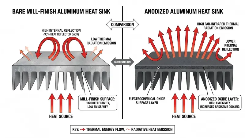
Applying an anodized surface treatment increases heat sink thermal emissivity by nearly 800%. This allows the heat sink to radiate far-infrared energy directly to colder surrounding surfaces (walls, floor, and structural racking), providing an additional thermal relief valve during peak photoperiods.
For a comprehensive evaluation of building HVAC loads, sensible heat ratios, and total thermal dissipation profiles in indoor facilities, refer to our detailed breakdown on LED grow light heat radiation and HVAC impact.
Passive Aluminum Heat Sinks vs. Active Fan Cooling: A Commercial Comparison
When selecting horticultural lighting fixtures, commercial operators frequently evaluate passive aluminum heat sink architectures against active fan-cooled designs.
While active fans allow manufacturers to use smaller heat sinks by forcing air through narrow channels, moving parts introduce operational risks in commercial cultivation environments.
| Engineering Criterion | Heavy-Duty Passive Aluminum Heat Sinks | Active Mechanical Fan Coolers |
| Primary cooling mechanism | Conduction + Natural Convection + Radiation | Forced Convection via Electric Motors |
| Ingress protection (IP rating) | IP65 / IP66 (Fully dust-tight and water-jet resistant) | IP20 / IP54 (Open air vents permit moisture and dust ingress) |
| Mechanical failure risk | Zero moving parts; zero risk of mechanical seizure | High; fan bearing failure leads to immediate thermal runaway |
| Humidity & chemical resistance | Impervious to 95% RH, sulfur vapor, and foliage sprays | Bearings corrode; fans clog with airborne dust, pollen, and salt |
| Acoustic noise output | 0 dB (100% Silent operation) | 45–65 dB per fixture (Significant cumulative room noise) |
| Parasitic power consumption | 0 Watts (100% of driver wattage goes to LEDs) | 5–15 Watts per fixture dedicated solely to powering fans |
| Maintenance requirements | Minimal; periodic dust blowing during room reset | High; routine fan blade cleaning, bearing lubrication, filter swaps |
| Operating lifespan (L90) | >50,000 to 100,000 Hours | Limited by fan motor lifespan (typically 20,000–30,000 Hours) |
Commercial growers operating high-humidity rooms (75%+ RH) or utilizing CO2 enrichment recognize that a single fan failure can destroy a fixture in minutes. When an active fan stops spinning, diode junction temperature surges past 130°C within seconds, causing permanent diode burnout.
Passively cooled fixtures eliminate this point of failure, delivering long-term peace of mind and stable photon efficacy.
For additional criteria on selecting commercial lighting hardware, consult our commercial LED grow light selection guide.
Heat Dissipation in Passive Grow Lights: SLTMAKS Commercial Lighting Thermal Management Engineering
At SLTMAKS, thermal engineering serves as the foundation of fixture design. Rather than reducing aluminum weight to lower initial manufacturing costs, SLTMAKS engineers passive lighting systems built for continuous commercial operation under demanding facility conditions.
SLTMAKS passive thermal architecture:
- 6063-T5 heavy extruded aluminum fins: High thermal conductivity for rapid heat spreading.
- High-dielectric metal-core PCB: Accelerated conductive heat transfer away from diode pads.
- Industry-leading samsung & osram diodes: Engineered for minimal thermal junction resistance.
- Fully anodized oxide finish: High emissivity (ε ≈ 0.88) for maximum far-infrared radiation.
- Conformal silicone potting & IP66 seal: Full environmental protection against moisture and dust.
Key Thermal Design Features
- High-purity 6063-T5 extrusions: Fixtures feature heavy-gauge extruded aluminum bars with engineered fin ratios, ensuring heat conducts rapidly away from high-density diode arrays.
- Phase-change thermal interface materials: Precision-applied TIM eliminates microscopic air gaps between the circuit board and heat sink base, keeping thermal resistance (RθTIM) at minimum levels.
- Anodized surface protection: Every aluminum profile receives an anodized finish that maximizes far-infrared radiative cooling while protecting the metal against corrosion from humidity and liquid nutrient overspray.
- IP65/IP66 sealed driverintegration: Fixtures incorporate heavy-duty industrial drivers (such as Sosen, Inventronics, or Mean Well) housed in waterproof, potted aluminum enclosures mounted to permit natural air circulation around all four sides.
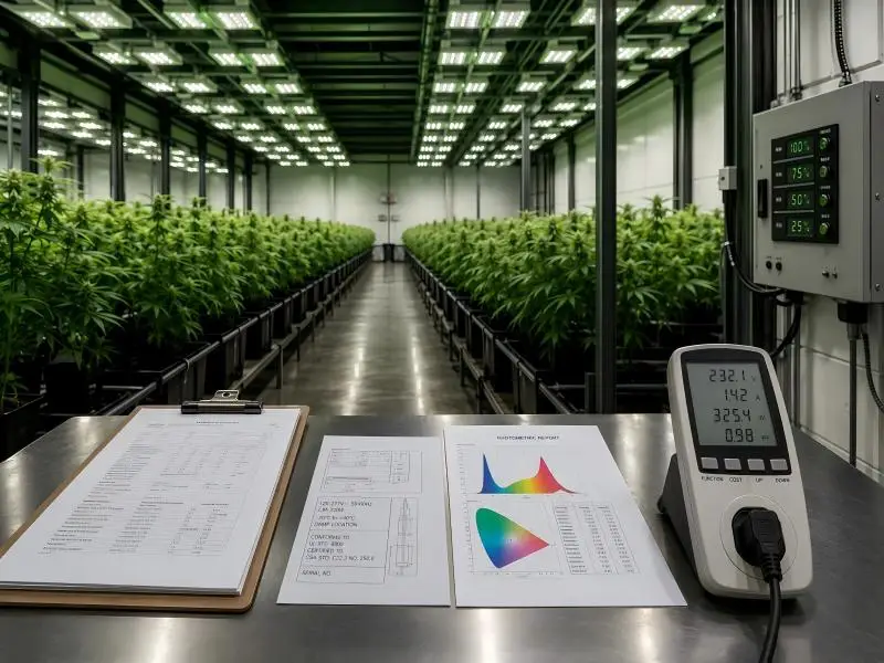
To review technical specifications, photometric reports, and fixture options engineered with heavy-duty passive cooling, explore the complete range of commercial indoor LED grow lights.
Facility Checklist: Optimizing Passive Thermal Dissipation
To ensure passive heat sinks operate at peak efficiency, facilities should incorporate these installation and maintenance guidelines into their standard operating procedures:
- Maintain minimum overhead clearance: Leave at least 8 to 12 inches (20 to 30 cm) of open space between the top of the heat sink fins and the ceiling or upper shelf. This prevents warm air from trapping above the fixture.
- Ensure vertical fin orientation: Verify that bar lights are mounted so that cooling fins align vertically with rising air plumes.
- Maintain gentle air movement: Ensure grow room circulation fans generate a soft horizontal air velocity of 0.3 to 0.5 m/s across the fixture zone. This breaks up stagnant boundary layers and increases convective heat transfer coefficients (h).
- Monitor canopy vs. fixture microclimates: Position environmental sensors at both the plant canopy level and the light fixture height to track vertical thermal stratification.
- Implement clean-down schedules: Blow dry compressed air across heat sink fins between crop cycles to remove accumulated dust or foliar spray residues that could insulate the aluminum surface.
FAQ
Why do passive LED fixtures not heat plant leaves like legacy HPS lights?
Legacy High-Pressure Sodium (HPS) fixtures project intense infrared radiation directly forward onto the crop canopy, elevating leaf surface temperatures. In contrast, LEDs emit minimal forward radiant heat; heat is conducted backward into the aluminum heat sink and dissipated upward via convection toward the ceiling, protecting sensitive canopy microclimates.
How does fin spacing influence natural convective air movement in grow rooms?
Unlike active fan-cooled systems that push air through narrow gaps, passive cooling relies on natural thermal buoyancy. If cooling fins are spaced too closely (under 5 mm), rising air forms a stagnant boundary layer that chokes convection. Passive horticultural heat sinks utilize wider fin spacing (typically 10 mm to 15 mm) to maximize natural convective airflow plumes.
Why is anodized aluminum better for passive cooling than bare raw aluminum?
Raw aluminum has an emissivity coefficient of roughly 0.05, meaning it reflects almost all internal radiant thermal energy. Anodizing creates a microporous oxide surface layer that increases emissivity to approximately 0.88. This enables the heat sink to radiate far-infrared heat directly into the surrounding environment, increasing passive cooling performance by up to 15%.
Next Steps for Facility Operators
Effective thermal management requires treating the light fixture and the facility environment as a single thermal system. By leveraging conduction through high-purity aluminum alloys, convection through optimized fin geometry, and radiation through anodized surface treatments, passive LED grow lights achieve industrial reliability with zero mechanical fan failure points.
If you are designing a new commercial cultivation facility or upgrading legacy HPS fixtures, contact the engineering team at SLTMAKS to request a custom light layout simulation, thermal analysis, and commercial fixture quotation.