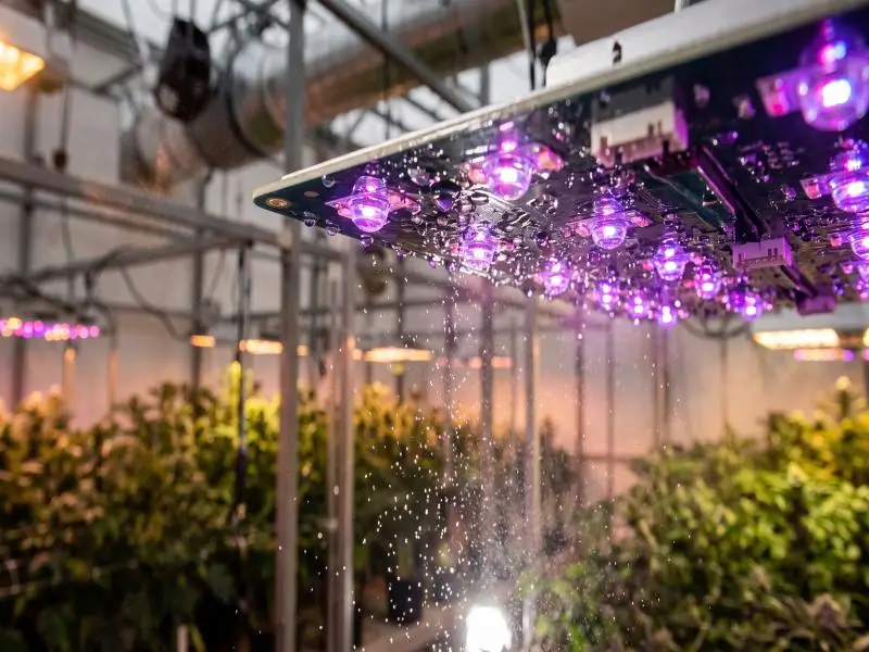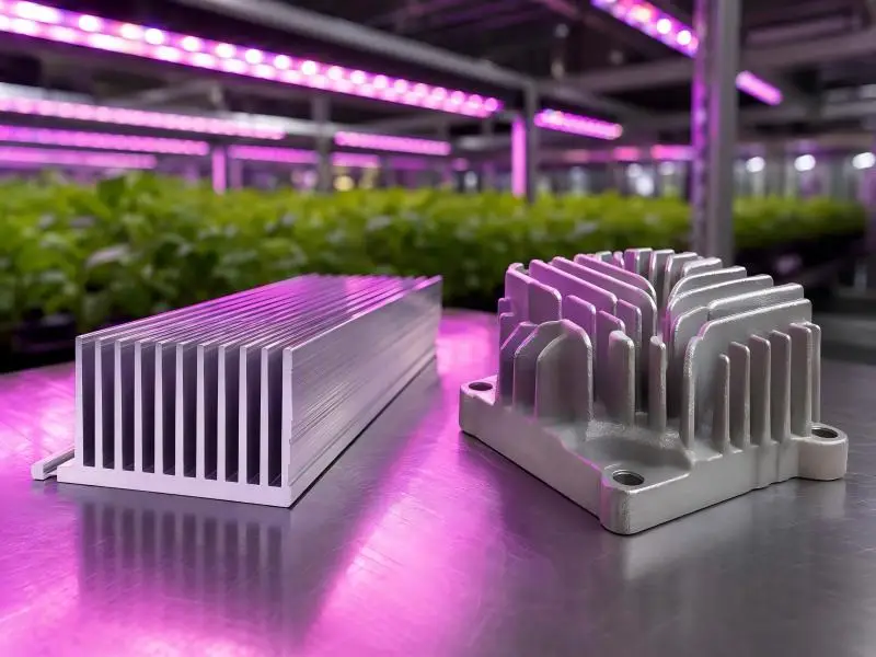
A driver failure in a multi-tier commercial grow room does not just kill light output. It stops the clock on your DLI accumulation, stalls crop scheduling, and puts your compliance posture at risk the moment an unqualified person picks up a screwdriver. For commercial indoor cultivation operators, every hour of dark canopy translates into real yield loss, HVAC over-cycling, and potential insurance exposure.
“Grow light driver repair” is a phrase that gets searched by technicians who already have a fixture down and need a fast answer. In practice, the phrase covers two very different situations: a straightforward driver swap that any qualified electrician can execute under proper lockout/tagout (LOTO), and a component-level board repair that rarely makes sense in a production facility. Knowing which situation you are in—before touching anything—determines how quickly you get back online and whether you stay on the right side of NFPA 70E and your authority having jurisdiction (AHJ).
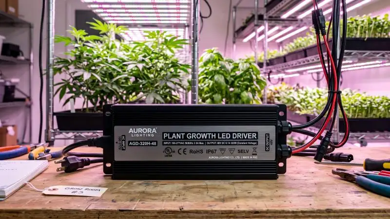
This guide walks you through the work safely, diagnoses the fault precisely, and gives you a clear decision framework for whether repair or replacement is the faster, lower-risk path for your operation.
Table of Contents
Work Safely First
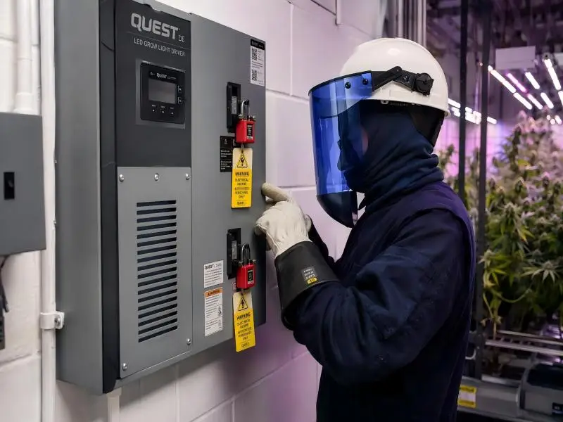
No diagnostic or repair work begins without establishing an electrically safe work condition (ESWC). In a commercial grow environment—high humidity, tight canopy clearances, live 277 V or 480 V distribution—this is not a procedural formality. It is how qualified persons come home.
Establish an ESWC (NFPA 70E)
NFPA 70E Article 120 defines an ESWC as the state achieved when all energy sources have been identified, isolated, locked out, released, and verified absent. Before your team begins, confirm you have:
- Up-to-date single-line diagrams or panel schedules that identify every supply circuit feeding the affected fixture row
- A written LOTO procedure for the specific equipment, as required by NFPA 70E 120.5(B) and OSHA 29 CFR 1910.333
- An assigned authorized employee responsible for the LOTO program execution when multiple workers are involved
For multi-crew environments, use a group lockout device and require every authorized employee to apply their individual lock. NFPA 70E 120.5(A)(4) defines when a simple versus complex LOTO procedure applies—complex procedures require a written sequential plan.
LOTO and Verify Absence of Voltage
Follow this sequence without skipping steps:
- Notify all affected personnel of the planned work scope
- Shut down using normal equipment controls
- Isolate at every energy source—open breakers, disconnects, or transfer switch as applicable; visually confirm the disconnect blade is open where possible
- Apply LOTO devices at each isolation point with locks and danger tags; for group work, use a group hasp
- Release stored energy—discharge driver capacitors by waiting a minimum of two minutes after isolation before touching output terminals; driver bus capacitors in high-power fixtures (≥600 W) can hold hazardous DC voltage well after AC input is removed
- Verify absence of voltage with a properly rated meter (CAT III 600 V or higher): test the meter on a known live source first (L-D-L sequence), then test phase-to-neutral and phase-to-ground at the fixture termination point
⚠️ Warning: Probing driver output terminals before confirming capacitor discharge has caused fatalities in lighting maintenance. The two-minute wait is not optional.
PPE and Energized Diagnostics Exceptions
All de-energized work requires insulated tools and safety glasses at minimum. If your diagnostic plan requires any measurement with the circuit energized—for example, verifying input voltage at the driver while the circuit is live—this constitutes energized electrical work under NFPA 70E. It requires:
- A documented Energized Electrical Work Permit from your site EHS program
- Arc-flash PPE selected from an incident energy analysis or the NFPA 70E PPE category tables for the relevant voltage and available fault current
- At least two qualified persons present
Most grow-room driver diagnostics do not require energized probing. Structure your procedure to keep everything de-energized wherever possible.
Quick Diagnostics
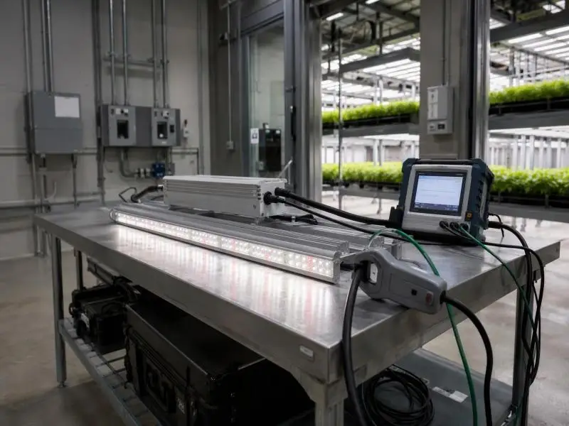
With the circuit de-energized and ESWC established, you can begin fault isolation. A methodical sequence takes less than 15 minutes and avoids the mistake of ordering a replacement driver when the LED board—or a simple connector—is the actual fault.
Visual Checks and Smell Tests
Before reaching for a meter, inspect the driver enclosure and the fixture body:
- Burn marks or carbonization on the driver housing, PCB, or surrounding fixture tray indicate a thermal event; do not attempt repair on fire-damaged equipment
- Bulging or leaking electrolytic capacitors on the driver PCB are a definitive replace signal—these failures are progressive and will recur
- Corrosion or moisture ingress inside the driver—white oxidation on terminals, rust traces on mounting hardware—suggests the IP rating has been breached
- Melted or discolored wiring at input or output connectors points to sustained overcurrent or a loose connection that arced
- Smell of burnt resin or ozone from the driver housing
If any of the above are present, stop diagnostic work and proceed directly to the replacement decision.
Input, Output, and Dimming Verification
For fixtures that pass visual inspection but show functional symptoms (no output, dimming not responding, flickering), measure systematically:
| Test Point | Expected Result | Failure Indication |
|---|---|---|
| Input voltage at driver terminals | Within ±10% of nameplate range | Upstream wiring or breaker issue, not the driver |
| Driver output voltage (open-circuit) | ≥ nameplate Voc | 0 V output with good input = driver fault |
| Driver output current under load | Within ±5% of nameplate Iout | Significant deviation = driver regulation failure |
| 0–10 V dimming signal | 0–10 V DC at driver dim terminals | Signal absent = controller or wiring issue |
| Driver temperature | < 75°C at housing (touch-safe threshold) | Thermal shutdown cycling = airflow or mounting problem |
For the swap test: if a known-good driver of the same specification is available on-site, disconnect the suspect driver and substitute it. If the fixture operates normally with the replacement driver, the fault is confirmed in the original unit.
Isolate Driver vs. LED Array Fault
When output voltage is present but light output is absent or significantly reduced, the LED board may be the fault rather than the driver:
- Measure voltage across the LED board input terminals with the driver connected and energized (energized work permit required)
- If voltage is present at the board and output is still absent, the LED array has failed
- If voltage collapses the moment load is connected but recovers open-circuit, the driver is limiting on overcurrent protection, which may indicate a short in the LED board
Distinguishing these two failure modes before ordering parts prevents the common mistake of replacing a functional driver on a fixture with a failed LED board.
Repair or Replace
Once the fault is localized, the decision framework is straightforward. Most commercial operations will land on replacement for almost every driver failure scenario.
When “Grow Light Driver Repair” Is Viable
Field-level repair is appropriate only when the fault is clearly external to the driver power stage:
- Loose or corroded output connector: clean the connector, crimp a new terminal if the contact is deformed, re-torque to manufacturer specification
- Blown input fuse: replace with an identical rated fuse; investigate why it blew before restoring power
- Damaged 0–10 V dimming wire: repair the control wiring run; verify signal integrity at the driver before re-energizing
- Incorrect dimming signal from controller: correct the controller configuration or replace a faulty controller output card
These are fixture-level corrections, not driver repairs. The driver power electronics are left untouched.
Component-level PCB repair—replacing capacitors, MOSFETs, bridge rectifiers, or control ICs on the driver board—requires certified electronics capability, component-level documentation the driver manufacturer typically does not release, and recertification by an NRTL before the driver can legally re-enter service in a listed fixture. In a production facility, this path is not practical.
Replace Criteria and Potted Unit Limits
Replace the driver immediately when any of the following apply:
- Physical damage: bulging capacitors, burn marks, cracked ICs, melted solder joints
- Electrical failure: output voltage or current outside specification with good input present
- Intermittent failure: thermal shutdown cycling, which indicates the driver is operating at its thermal limit and will fail again under grow-room conditions
- Repeated failure of the same model across multiple fixtures in a row (pattern failure)
- The driver is potted (encapsulated in resin): potted units are sealed by design and are not field-serviceable at the component level
For potted drivers, replace the unit. The resin encapsulation is an intentional design choice for humidity and vibration resistance—it also makes component access impossible without destroying the unit.
Cost, Downtime, and Risk Thresholds
Run a simple downtime cost calculation before debating repair economics. A 1,000 µmol/m²/s commercial room losing 24 hours of light during a critical flowering period carries a real yield cost that typically exceeds the driver replacement cost several times over.
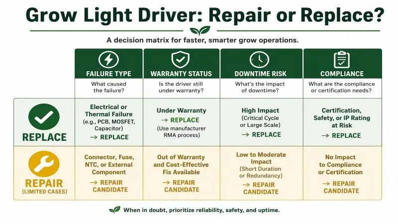
Use this threshold decision:
- Replace if the driver is within its warranty period (most commercial drivers carry 3–5 year warranties; file the claim and get the replacement driver shipped)
- Replace if the total cost of repair labor exceeds 40% of driver replacement cost
- Replace if the failure type involves power electronics (not just external connectors or control wiring)
- Replace the fixture if the driver is proprietary to a specific fixture generation, no longer available as a spare part, or if the LED board has also failed
Pro Tip: Maintain a real-time downtime log. Recurring failures in a specific driver model across your facility are a procurement and quality signal—not just a maintenance event.
Select a Compliant Replacement
Sourcing the wrong replacement driver is a compliance event, not just a technical mistake. A driver swap that changes the fixture’s certification basis voids the NRTL listing and may require AHJ re-inspection before the fixture can legally re-enter service.
Match Current, Voltage, and Dimming
The replacement driver must match the original on every electrical parameter:
- Driver type: constant-current (CC) for LED boards with a specified forward current, constant-voltage (CV) for certain distributed LED configurations—never substitute one for the other
- Output current: exact match to the original specification (e.g., 2,800 mA, not a close approximation)
- Output voltage range: replacement Vout range must span the LED board’s forward voltage at rated current
- Input voltage: must cover your facility’s distribution voltage (120 V, 208 V, 277 V, 347 V, or 480 V as applicable)
- Dimming protocol: 0–10 V and DALI are not interchangeable; confirm the control system compatibility
- Power factor and THD: commercial facilities targeting utility rebates often require PF ≥ 0.90 and THD < 20%—verify the replacement meets these thresholds
For constant-current vs. constant-voltage driver selection, confirm the driver’s over-voltage protection (OVP), over-current protection (OCP), and short-circuit protection behavior align with the LED board’s requirements.
Maintain UL/ETL Listing Integrity
A replacement driver must be listed by an OSHA-recognized Nationally Recognized Testing Laboratory (NRTL) to the applicable safety standard. For horticultural lighting in North America, the relevant standards are:
- UL 8800: specifically addresses horticultural luminaires and the high-humidity, high-moisture environments of commercial grow rooms
- UL 8750: covers LED equipment used in lighting systems generally
- ETL listing: interchangeable with UL listing for AHJ acceptance purposes when the listing is to the same standard
Do not accept a supplier’s PDF test report as a substitute for an active listing. Verify the driver’s listing by searching the manufacturer and model number in the UL Product iQ database or the Intertek ETL directory directly.
When the replacement driver is from a different manufacturer than the original, confirm with your fixture’s manufacturer whether the substitution preserves the fixture’s system-level listing. Some fixture certifications are model-specific; a driver substitution may require a letter of authorization from the fixture manufacturer.
Practical guidance on compliant replacement sourcing: Fixtures that carry ETL, CE, and RoHS certifications at the system level—and that specify listed drivers such as Mean Well, Inventronics, Sosen, or equivalent NRTL-certified units—provide a cleaner spare-parts path because the driver is a documented, separately replaceable component. SLTMAKS fixtures, for example, use ETL-listed and CE-certified drivers with passive aluminum thermal management sized for humid commercial environments, which simplifies documentation when an AHJ requires evidence that the replaced component maintains the original listing basis.
Warranty, Documentation, and Labeling
Before the replacement driver goes into service:
- Retain the driver’s original packaging with the model number, lot code, and listing marks intact for your maintenance records
- Photograph the installed driver label before closing the fixture housing—this creates a timestamped record for your next AHJ inspection
- Update your CMMS or maintenance log with the driver model, serial number, installation date, and the technician’s qualified person credential
- If the original fixture was covered by the luminaire manufacturer’s warranty, notify the manufacturer that a driver swap occurred; this preserves your documentation chain and may trigger a warranty replacement if the driver failure was within the coverage period
Wiring and Compatibility Checklist
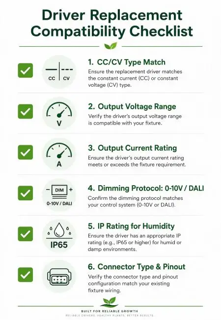
Before re-energizing the replaced driver, verify each item:
| Check | Pass Criterion |
|---|---|
| CC/CV type match | Replacement type matches original driver type exactly |
| Output voltage range | Replacement Vout range covers LED board Vf at rated Iout |
| Output current rating | Exact match to original nameplate (±0–5%) |
| Dimming protocol | 0–10 V or DALI confirmed against control system |
| IP rating | ≥ IP65 for grow rooms; ≥ IP67 for high-pressure wash-down zones |
| Connector type and pinout | Mating connector confirmed; no pin-swap or adapter substitution |
Prevent and Prepare
A reactive maintenance posture in a commercial grow facility is a yield-risk posture. The goal is to catch driver degradation before it becomes a dark-room event.
Thermal Management in Humid Rooms
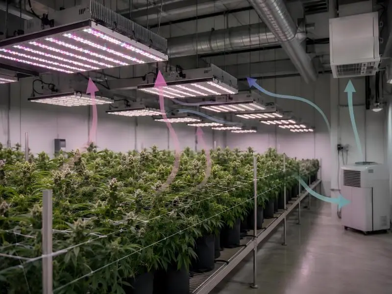
Elevated ambient temperature is the primary driver life-limiting factor. Most commercial grow light drivers are rated for an ambient operating range of −20 °C to +45 °C at the driver compartment—not at the room air temperature. In high-density canopy rooms with inadequate air exchange, driver compartment temperatures can exceed ambient by 10–15 °C.
Practical steps:
- Measure driver housing temperature with an IR thermometer during peak load; readings above 75 °C at the housing surface are a degradation risk signal
- Verify that supply air reaches the driver compartment, not just the canopy level; stratified warm air above the canopy accelerates driver aging
- Passive aluminum heat sinks on the fixture body are only effective when air can circulate freely; do not stack fixtures against HVAC ductwork or cable trays that block convective flow
- In rooms above 35 °C ambient, derate driver load per the manufacturer’s thermal derating curve—running at 100% rated power at elevated ambient dramatically shortens electrolytic capacitor life
Surge Protection and Power Quality
Commercial distribution networks serving large facilities experience voltage transients from motor starts, capacitor bank switching, and utility events. LED drivers without adequate surge protection fail at rates disproportionate to their nominal MTBF.
- Specify drivers with surge immunity of ≥ 4 kV (differential mode) per IEC 61000-4-5; this is not a luxury spec for commercial operations—it is a baseline
- Install transient voltage surge suppressors (TVSS) at distribution panels serving grow rooms, coordinated with the driver’s internal surge rating
- Monitor power quality at the panel feeding each grow room at least annually—harmonic distortion from variable-frequency drives controlling irrigation or HVAC equipment can contribute to driver overheating over time
- For inrush current management at scale, review the LED grow light inrush current guidance before sizing circuit breakers for new or expanded driver rows
Spares Strategy and SKU Standardization
The fastest recovery from a driver failure is pulling a spare from the shelf. In multi-fixture facilities, the economics of standardization make the spare-parts decision straightforward.
- SKU standardization: limit your active fixture models to the minimum required to meet crop-specific spectrum or intensity needs; each additional fixture model adds a spare-parts SKU with its own procurement, storage, and documentation overhead
- Spares ratio: for rooms with 50+ fixtures, maintain a minimum 5% on-hand spare driver pool for each active driver model; for smaller rooms, one spare per driver model is the minimum practical floor
- Sourcing lead time: track lead times for each driver model quarterly; supply chain disruptions have pushed some commercial driver lead times to 8–14 weeks; if a model goes end-of-life, execute a planned transition to a listed equivalent before stock runs out
- Documentation package per spare: each spare driver in stock should have a copy of its datasheet, listing certificate, and compatibility confirmation for the specific fixture it is approved to replace—this eliminates per-event research when a failure occurs at 2 AM during flower week
Conclusion
A commercial indoor grow light driver failure is a recoverable event when the response is structured. The sequence is non-negotiable: establish an ESWC under NFPA 70E before any diagnostic work, isolate the fault to the driver or the LED board before ordering parts, and apply the repair-or-replace decision criteria to minimize both downtime and compliance risk.
In most commercial facility scenarios, grow light driver repair means driver replacement—not component-level board work. The cost threshold, the recertification burden, and the productivity cost of extended downtime make replacement the economically and operationally correct choice for any failure involving the driver power electronics.
Key takeaways for your team:
- Establish ESWC and discharge capacitors before any hands-on work—no exceptions
- Visual inspection eliminates most ambiguity: burn marks, bulging caps, or moisture ingress = replace immediately
- A potted driver is a non-serviceable driver; order the replacement, not the repair
- Replacement driver must match on CC/CV type, current, voltage, dimming protocol, IP rating, and NRTL listing
- Voiding the fixture’s NRTL listing through a non-compliant driver swap creates AHJ inspection risk
Next steps to reduce future downtime:
- Audit your driver compartment temperatures during peak load and compare against nameplate derating curves
- Confirm surge protection ratings at the distribution panels serving your grow rooms
- Standardize on a minimum set of fixture models and build a documented spare-driver inventory for each
- Establish a recurring driver inspection cadence—visual inspection and thermal scan every 6 months—to catch degradation before it causes unplanned downtime
If you are evaluating replacement fixtures or sourcing spare drivers for your facility, talk to the SLTMAKS technical team for specification support and documentation packages that match your AHJ’s requirements.
FAQ
Why do grow light drivers fail, and how long should they last?
Why do grow light drivers fail, and how long should they last?
Heat is the driver’s primary enemy. Electrolytic capacitors inside the driver age roughly twice as fast for every 10 °C rise in internal temperature, which is why drivers — not the LEDs — are usually the first component to fail in a well-designed fixture. Expect 30,000 to 50,000 hours from a quality commercial driver under normal conditions, though power surges, moisture ingress, and sustained over-temperature all shorten that window. The safest assumption is that the LED board will outlive the driver, so plan your maintenance around the driver first.
Should I repair my grow light driver or just replace it?
Should I repair my grow light driver or just replace it?
In a commercial facility, replace the driver unless the fault is clearly external to the power stage — a corroded connector, a blown input fuse, or a damaged dimming wire. Component-level PCB repair (replacing capacitors, MOSFETs, or control ICs) requires electronics certification, manufacturer documentation you usually can’t get, and NRTL recertification before the driver can legally return to service. As a rule of thumb: if the repair involves anything inside the driver’s power electronics, or the driver is potted (resin-encapsulated), order a compliant replacement instead.
How much does it cost to replace a grow light driver?
How much does it cost to replace a grow light driver?
A replacement driver typically runs $15 to $80 for the part, with professional installation adding $50 to $150 in labor — around $65 to $230 all-in, depending on the fixture class and your local rates. Before comparing that against a repair quote, add the yield cost of downtime during a critical growth phase; a dark 1,000 µmol/m²/s room can lose more value in a single day than the driver swap costs. If the fixture is under warranty, always file the claim first — that path is usually free and fastest.