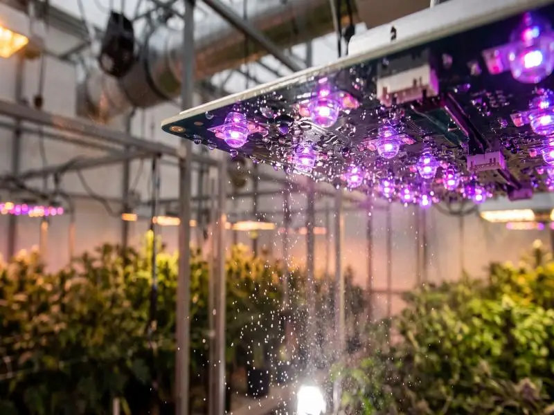
Conformal coating LED grow lights is the step that decides whether a humid cultivation room destroys your fixtures or merely ages them. The stakes are measurable: in one outdoor LED luminaire model tracked across a combined 212 million field operation hours, over 70% of failure modes were traced to the driver, not the LEDs (IEA 4E SSL Annex and the Lighting Research Center, 2021). That study covers outdoor general lighting, not grow rooms, and its own authors warn the result cannot be generalised. It still tells you where to look first: driver boards, terminals and cable entries, the surfaces that sit wettest in a high-VPD room.
The mechanism is not mysterious. Humid air adsorbs onto laminates, solder-mask defects, and connector interfaces, and above roughly 60% RH ionic residues can become conductive; condensation forms whenever a fixture cools below dew point, repeatedly wetting the same spots, and under DC bias dissolved metal migrates through that moisture film and redeposits as branched filaments (PCBCart, 2026). Grow rooms add a second layer: nutrient mist leaves hygroscopic fertilizer salts on fixtures, and those salts hold moisture and raise conductivity above what clean water would produce (Atop Lighting, 2026).
This guide is written for operators and reliability engineers who already run LEDs and now need to specify, qualify, and audit coated assemblies. It covers the failure modes your environment actually produces, the coating chemistries and their honest limits, the optical and thermal constraints that decide whether a coating is acceptable at all, the process and quality controls that make a coating claim verifiable, and the standards and cost model you need to defend the decision to procurement.
Table of Contents
Grow-Room Risks and Failure Modes
The criterion to settle first is which failure mode your room produces, because moisture, chemistry, and bias do not act alone. Electrochemical migration (ECM) requires three conditions simultaneously: ionic carriers, a medium (usually water) to dissolve and mobilise them, and an electrical potential between electrodes, and failure sites appear wherever moisture, oppositely biased conductors, and contamination coexist (NASA Goddard, PCB Inspection and Quality Control, 2018). Remove any one of the three and the mechanism stops.
Humidity, Condensation, and Aerosols
Condensation, not ambient humidity, does most of the damage. A fixture that cycles on and off cools below dew point between photoperiods, and the resulting film wets driver boards, terminals, cable entries, and heat-sink interfaces repeatedly. The flux-residue study by Lakkaraju and colleagues, published in a peer-reviewed journal in 2025, tracked this directly: the lag between air temperature and PCBA surface temperature causes condensation and water-layer formation, which then lets moisture reach the flux residues trapped under components (Lakkaraju et al., 2025).
Aerosols change the chemistry of that water. Fertilizer and nutrient mist deposits hygroscopic salts that absorb moisture and form a thin electrolyte, raising conductivity and corrosion rates above those of clean water, while pesticide and disinfectant residues can attack solder, copper, silver, aluminium, and connector plating (Atop Lighting, 2026). An IP rating does not guarantee chemical resistance, so a fixture rated for wet locations can still corrode in a fertigated room.
Corrosion, Leakage, and Dendritic Growth
Dendritic growth is the ECM form involving conductive filaments on or in a board under DC bias, per IPC-TR-476A, and its failure modes are electrical shorts and a drop in surface insulation resistance (NASA Goddard, 2018). The stages run in sequence: path formation, electrodissolution, ion transport, electrodeposition, filament growth. Because the fragile dendrite burns away when it shorts, the failure site is often impossible to find afterwards, which is why intermittent faults in humid rooms so rarely get a clean root cause.
Contamination thresholds give you a measurable target. ECM risk tends to increase once chloride exceeds 10 µg/in² or bromide exceeds 15 µg/in², and rapid failure can occur above 50 µg/in² of contaminant (NASA Goddard, 2018). Leakage current gives you an earlier warning: a critical leakage current of 0.01 µA marks incipient dendrite formation on biased PCBA test structures, and peak currents in the region of 1 µA were measured on some component and flux combinations, two orders of magnitude above that threshold (Lakkaraju et al., 2025).
Sulfur Exposure and Connector/Driver Vulnerabilities
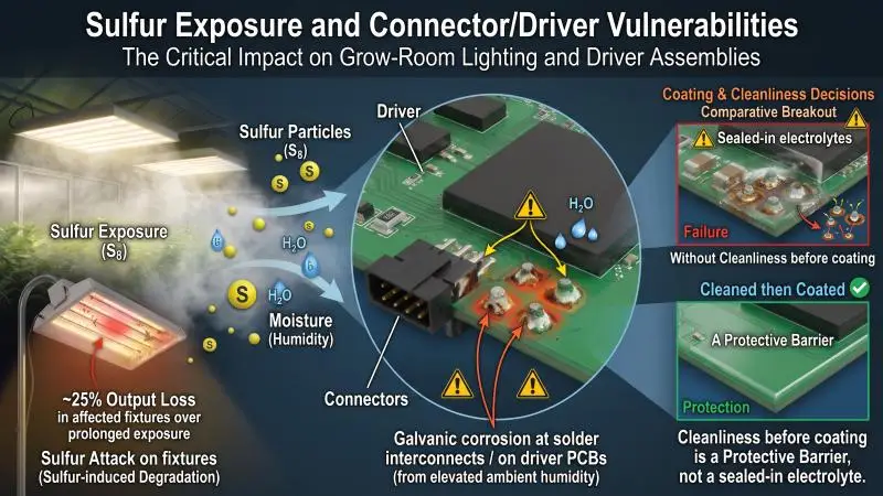
Sulfur is the grow-room hazard that most coating specifications ignore. One grow-light technical source reports roughly 25% output loss in affected fixtures over prolonged exposure; treat that figure as single-source and verify it against your own field returns before quoting it.
The driver remains the most exposed assembly. The IEA 4E review records galvanic corrosion at solder interconnects on driver PCBs caused by elevated ambient humidity, which the authors state can be reduced by cleaning the assembly after soldering (IEA 4E SSL Annex and the Lighting Research Center, 2021). That finding matters for coating decisions: cleanliness before coating is not a housekeeping detail; it is the difference between a barrier and a sealed-in electrolyte.
Key Takeaway ECM needs moisture, ionic contamination and DC bias at the same location. Coating removes the moisture path, cleaning removes the ions, and neither substitutes for the other.
The chemistry you choose to break that chain is the subject of the next section.
Coating Chemistries and Trade-offs
The criterion here is which chemistry survives your room’s temperature, chemistry, and rework model, because no single coating wins on every axis. The governing standard classifies coatings by cured chemistry: Type AR (acrylic), ER (epoxy), SR (silicone), UR (polyurethane), XY (paraxylylene), SC (styrene block co-polymer), with any coating targeting 12.5 µm [0.49 mil] or less defined as Type UT regardless of chemistry (IPC-CC-830C, December 2018).
Acrylic, Silicone, Polyurethane, Epoxy, Parylene
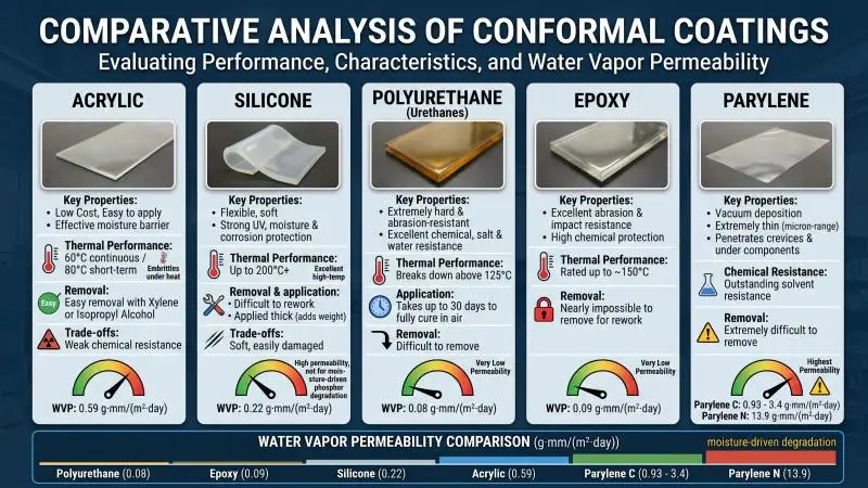
Acrylics give an effective moisture barrier at low cost and remove easily with xylene or isopropyl alcohol, but that same solubility means weak chemical resistance, and acrylics embrittle under prolonged heat with a chart service temperature of 60 °C continuous and 80 °C short-term (Conformal Coatings 101, Specialty Coating Systems).
Silicones withstand temperatures up to about 200 °C, with special formulations higher, and provide strong protection against moisture, humidity, corrosion, and UV, but they are soft, easily damaged, and often applied in thick layers that limit use where coating weight or tight thickness tolerance matters.
Urethanes are cited for chemical, salt, and liquid-water resistance and are among the hardest coatings available, though they commonly break down above 125 °C and can take as long as 30 days to fully cure in air.
Epoxies are abrasion-resistant and rated to around 150 °C but are nearly impossible to remove for rework, and polyimides are applied by vacuum deposition in the micron range, penetrate crevices and under components, and resist solvents so well that removal becomes the problem.
Water-vapour permeability separates the chemistries more sharply than marketing language does. Reported permeability in g·mm/(m²·day) is 0.08 for polyurethane, 0.09 for epoxy, 0.22 for silicone, 0.59 for acrylic, and 0.93 to 3.4 for Parylene C, with Parylene N at 13.9 (Specialty Coating Systems). Silicone’s higher permeability is not a defect in every application, but it is the reason the DOE colour-shift work recommends less water-permeable binders where moisture-driven phosphor degradation is the concern.
Optical, Chemical, and Rework Considerations
Coating selection for LED protection has its own criteria list: high transparency and yellowing resistance, low optical attenuation, colourless films, and resistance across the visible wavelength range even in thick layers or under permanent high temperature, with the silicone-resin grade quoted in that guide rated for 150 °C stability (Peters, TI 15/20, 2024). Note the vendor context: that document is a coating supplier’s selection guide, useful for criteria, not neutral qualification evidence.
Rework is where the trade-off becomes operational. The DOWSIL 1-2577 data sheet gives a 3 mil (75 µm) cure schedule of 10 minutes at room temperature followed by 10 minutes at 80 °C, a dielectric strength of 340 V/mil, UL 94 V-0/V-1 flammability, and removal by scraping, cutting, solvents, or stripping agents, with a soldering iron applicable directly through the coating to rework one component (DOWSIL 1-2577 data sheet). That last property is the practical argument for silicone in multi-site operations where a single failed component should not scrap an assembly.
Matching Coating to Environment and Service Model
| Chemistry (IPC type) | Water-vapour permeability, g·mm/(m²·day) | Chemical/solvent resistance | Rework | Service temperature | Typical thickness |
|---|---|---|---|---|---|
| Acrylic (AR) | 0.59 | Low | Easy, solvent-based | 60 °C continuous / 80 °C short-term | 0.001–0.005 in |
| Epoxy (ER) | 0.09 | High | Very difficult | ~150 °C max | 1–5 mils |
| Polyurethane (UR) | 0.08 | High (salt, chemicals) | Difficult | Breaks down above 125 °C | 1–5 mils |
| Silicone (SR) | 0.22 | Low solvent resistance | Easy | Up to ~200 °C | Often thick |
| Parylene (XY) | 0.93–3.4 (C); 13.9 (N) | Very high | Very difficult | Up to 350 °C long-term (HT) | Microns |
| Ultra-thin (UT) | Chemistry-dependent | Chemistry-dependent | Chemistry-dependent | Chemistry-dependent | ≤12.5 µm |
Sources: permeability and service temperatures from Specialty Coating Systems; type classification and the 12.5 µm threshold from IPC-CC-830C; thickness band from MG Chemicals, 2021.
The decision rule that falls out of the table: urethane or epoxy where agrochemical exposure dominates and rework is rare, silicone where temperature range and repairability dominate and thickness tolerance is loose, acrylic only for dry or lightly humid rooms with frequent rework, and parylene where crevice penetration matters more than cost. Where a board must survive both high temperature and aggressive chemistry, the honest answer is that no single coating does both well, and the specification should say so.
Optical and Thermal Impacts on LEDs
The criterion is whether coating changes PPFD or junction temperature, and the evidence base here is thinner than vendors imply. No source located for this guide states a measured PPFD or light-loss percentage for a conformal-coated LED grow-light board at a stated thickness, so any figure you see quoted for that specific claim should be treated as unverified until the supplier produces transmission data for the exact chemistry and film thickness.
Protecting Optics and PPFD Consistency
The nearest primary optical data is for secondary optics, not coating. High-quality PMMA or PC lenses over LEDs introduce transmission losses typically of 5% to 12%, depending on material, geometry, and the number of optical surfaces (Lumistrips). That is an order-of-magnitude ceiling for optical loss in the assembly, and it belongs to the lens, not the coating. A coating applied correctly to the board, with the emitter and lens masked, is not the main optical loss mechanism in a well-specified fixture.
Junction Temperature, Thickness, and Keep-out Zones
Masking the LED and connector keep-out zones is mandatory, not optional. Coating the emitting surface can reduce light output or alter colour and can interfere with connections, which is why masking and selective, often robotic, application are used to restrict coating to the PCB (AllPCB, 2025). A coating that creeps onto the lens or bridges a connector has failed the optical requirement regardless of how well it passed the moisture test.
Thermally, the case for coating over potting is straightforward. Potting fully submerges electronics in resin: waterproof, but it eliminates rework, may dim light or shift colour, and impedes heat dissipation, which can drastically reduce LED life, whereas conformal coating is thin enough to preserve thermal dissipation and removable for repair, though it is not as waterproof as potting and works best combined with sealed packaging (Techspray, 2025). Vendor context applies: Techspray sells coating, so read that as a trade-off statement rather than a neutral verdict.
Warning Coating the emitting surface reduces output and shifts colour. Specify keep-out zones for the LED, lens and connectors, and verify them on the first article before production release.
Validating Flux, Spectra, and Color Shift over Time
Colour shift is a system-level problem, not a chip problem. The DOE report concludes that chromaticity shift usually originates in the emitter, phosphor, encapsulant, package, reflector, lens, diffuser, or adhesives, and that the presence of moisture around phosphor particles and their neighbouring binder affects the rate of shift (US Department of Energy, LED Luminaire Reliability, 2017).
ENERGY STAR qualification requires 9 of 10 samples to hold Δu’v’ below 0.007 over the first 6,000 hours; in accelerated testing, cool-white high-power LEDs shifted 0.012 toward yellow and warm-white 0.028 toward green after 3,500 hours at 75 °C/75% RH, and the warm-white peak moved from 610 nm to 580 nm after 4,000 hours at 85/85, a step corresponding to roughly 4× acceleration. Those are uncoated-LED baselines, not coating effects, and no source found here gives a coated-versus-uncoated colour-shift comparison.
The mechanism connects back to the chemistry section. Red nitride phosphors in warm-white LEDs shift under oxidation, and when combined with silicone binders they show larger chromaticity shifts in wet high-temperature operating life testing because of silicone’s high water permeability; the shift can be mitigated by selecting less water-permeable binders such as polyurethane (US Department of Energy, 2017). That is the same permeability trade-off the coating table above quantifies, which is why a coating decision and a colour-stability decision should be made together rather than in separate procurement tracks.
Process and QA for LED PCB Assemblies
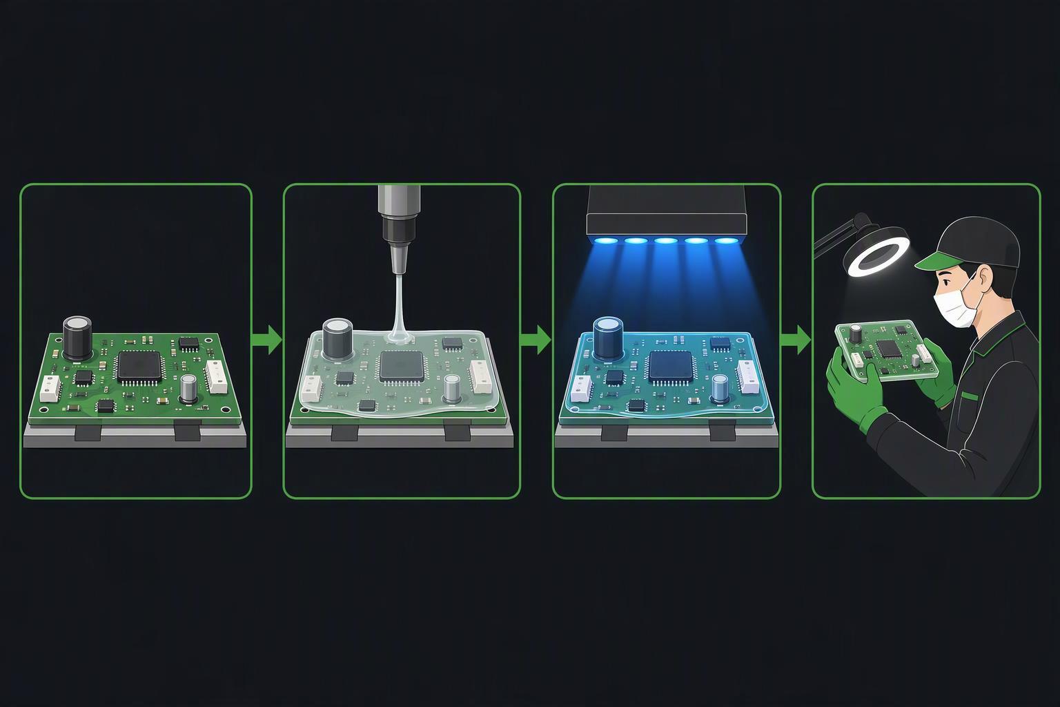
The criterion is whether the coating process is verifiable, because an unverifiable coating claim is worth nothing in a warranty dispute. A defensible sequence runs specification, cleanliness verification, masking, first-article application, cure validation, visual and UV inspection, thickness verification, then electrical and functional release, with UV fluorescence used only to confirm the presence and boundaries of coating; fluorescence does not prove thickness, adhesion or cure (conformalcoating.co.uk process control, 2026).
Surface Prep, Masking, and Selective Application
Cleaning comes first because contamination defeats the barrier. De-wetting occurs when flux, grease, oil, or cutting fluid remain on the surface and prevent the coating from spreading and levelling, and the remedy is thorough cleaning until no contaminants remain; masking then protects keep-out areas, and masking material should be removed soon after application and before the coating cures to avoid peeling away cured film (MG Chemicals, 2021). Trapped moisture under low-standoff components is the failure mode to watch: it is sealed in, not excluded, when the board goes into the chamber wet.
Cure Validation, UV/Visual Inspection, Thickness Control
Thickness is the number your specification should carry. Typical dry film thickness for conformal coatings runs from 1 to 5 mils (25.4 to 127 µm), verified by micrometer comparison before and after coating, by a digital coating thickness gauge on conductive substrates, or by cross-section analysis where the highest accuracy is needed (MG Chemicals, 2021). The gauge method cannot measure over solder mask or insulated components, which is exactly where many LED boards need coverage, so plan the measurement locations and witness coupons before the first production run.
Cure schedules are chemistry-specific and should be taken from the data sheet rather than assumed. The DOWSIL 1-2577 data sheet’s 3 mil schedule of 10 minutes at room temperature plus 10 minutes at 80 °C is a cure reference, not a design recommendation for LED boards, and treating it as the latter is a common specification error (DOWSIL 1-2577 data sheet).
Pro Tip UV inspection confirms coverage, not thickness or cure. Pair every black-lamp check with a measured thickness reading at defined locations, or you are documenting fluorescence rather than protection.
Reworkability, Documentation, and Change Control
Documentation is what makes a coating claim auditable across sites. The process-control sequence above should be recorded per batch with thickness readings at defined locations against process position, using witness coupons where they are representative, and the coating material’s qualification certificate should be filed with the batch record rather than the purchase order.
Change control deserves the same discipline. A switch of flux, a change of coating supplier, or a shift from hand spray to selective robotic application each changes the failure physics, and each should trigger re-qualification rather than a note in a file.
Compliance, Testing, and ROI
The criterion is which certificate actually answers your question, because the most commonly cited documents do not. IPC-CC-830C, the current revision of the conformal coating qualification standard, is explicit that it covers materials qualification and conformance only, not materials application or performance in the end-use environment (IPC-CC-830C, December 2018). A passing certificate tells you the material passed a standard battery; it does not tell you the coated board will survive your room.
Standards: IPC-CC-830, UL 746E/UL 94, IEC 60529, IEC 60068
| Standard | What it covers | What it does not cover |
|---|---|---|
| IPC-CC-830C | Coating material qualification and conformance; type classification (AR, ER, SR, UR, XY, UT, SC); 12.5 µm ultra-thin threshold | Application process or end-use performance |
| IPC-TM-650 2.6.3.3B | Surface insulation resistance under humid bias: 85 ± 2 °C, 85 ± 2% RH, 168 h, 45–50 VDC through a 1 MΩ resistor; dendritic growth spanning ≥25% of conductor spacing = failure | Coated production assemblies (standardised test vehicles only) |
| UL 746E / UL 94 | Dielectric properties after environmental stress; flame retardancy | Moisture-barrier performance in service |
| IEC 60529 (IP code) | Enclosure protection: solids 0–6, water 0–9 | Coating performance; chemical resistance |
| IEC 60068-2-30 | Cyclic damp heat: 24-hour cycles to +55 °C at ~93% RH, commonly 6 cycles (144 h) | Steady-state 85/85 conditions |
Sources: IPC-CC-830C; IPC-TM-650 2.6.3.3B; MG Chemicals, 2025; ITM Lab.
The IP code is the most misread of these. It rates the protection an enclosure provides against solid and water ingress, with the first digit covering solids and the second covering liquids, and IEC states plainly that water ratings are not fully cumulative: protection against immersion does not imply protection against powerful jets, and vice versa (IEC). An IP65 fixture is not thereby protected against fertilizer salts or sulfur, because the code does not test for either.
Assembly Qualification: 85/85, Condensation Cycling, Mixed-Flowing-Gas
The IPC-CC-830 qualification battery is material, and it is worth knowing exactly what it contains: dielectric withstanding voltage at 1500 VDC for 1 minute, thermal shock cycling between −65 °C and +125 °C for 24 hours, moisture insulation resistance with samples incubated in high humidity under 50 VDC requiring insulation of at least 5×10⁹ Ω, plus hydrolytic stability, fungus resistance, flexibility by 180° bend over a mandrel, and flammability (MG Chemicals, 2025). Those are material properties measured on standardised test vehicles.
For your own assemblies, specify the test that matches the room. IPC-TM-650 method 2.6.3.3 runs surface insulation resistance at 85 ± 2 °C and 85 ± 2% RH for 168 hours with a 45–50 VDC bias through a 1 MΩ limiting resistor, with readings at 24, 96 and 168 hours, and treats dendritic growth spanning 25% or more of the original conductor spacing as a failure (IPC-TM-650 2.6.3.3B). Note the method’s own warning: if condensation forms on specimens under voltage, dendritic growth will occur, so chamber control matters as much as the pass criterion.
Cyclic damp heat covers the condensation case that steady-state testing misses. IEC 60068-2-30 uses 24-hour cycles from +25 °C to +55 °C with humidity range 95% RH, commonly run for six cycles (144 hours) (ITM Lab). For grow rooms, a mixed-flowing-gas or salt-fog run adds the agrochemical dimension that neither humidity test captures. One caution on interpreting accelerated results: the IEA 4E review records Lall et al. observing catastrophic, top-blown IGBT and MOSFET failures under 85/85 that were surge-driven rather than the parametric degradation the DOE colour-shift work tracks, so a single accelerated test does not predict every field failure mode (IEA 4E SSL Annex and the Lighting Research Center, 2021).
Uptime, Maintenance Intervals, and TCO Modeling
No source found for this guide publishes a maintenance-interval extension in months or years attributable to coating in humid grow rooms, so the cost model has to be built from your own site data rather than borrowed benchmarks. The structure that works:
Annual cost of uncoated = (fixture failure rate × fixtures) × (fixture cost + labour rate × swap hours) + (unplanned downtime hours × revenue per hour)
Annual cost of coated = (fixture failure rate × reduction factor × fixtures) × (fixture cost + labour rate × swap hours) + coating cost per fixture + qualification cost amortised over the fleet
The reduction factor is the number you must generate yourself, from a coated-versus-uncoated pilot in the same room over the same photoperiod. No published figure substitutes for it. What the evidence does support is the direction of the trade: coating is thin enough to preserve thermal dissipation and removable for repair, unlike potting, which eliminates rework and impedes heat dissipation (Techspray, 2025). The avoided costs that typically dominate the model are site visits, expedited spares, and mid-cycle fixture swaps, not the coating material itself.
If you are specifying coated assemblies for a new build or a retrofit, talk to an expert or request qualification documentation before you write the purchase specification, so the thickness, chemistry, and test conditions in the spec match what the supplier can actually certify.
Conclusion
Conformal coating LED grow lights is a specification decision, not a product feature, and the evidence supports a clear sequence. Start from the failure mode your room produces: condensation on driver boards and terminals, hygroscopic fertilizer salts, and sulfur attack on silver-plated reflectors. Break the ECM chain by removing ions through cleaning and removing the moisture path through coating, because neither step substitutes for the other. Choose the chemistry against your actual constraints, using the permeability and service-temperature trade-offs rather than a supplier’s preference, and accept that no single coating wins on moisture barrier, chemical resistance, temperature range, and reworkability at once.
Then make the claim verifiable. Specify thickness within the 1 to 5 mil band, mask the LED, lens, and connector keep-out zones, validate cure against the data sheet schedule, and pair every UV inspection with a measured thickness reading. Qualify against the test that matches your room, whether that is 85/85 surface insulation resistance, cyclic damp heat, or a mixed-flowing-gas run, and read IPC-CC-830C for what it is: a material qualification standard that says nothing about your end-use environment.
The next step is a coated-versus-uncoated pilot in one room, with the same photoperiod and the same maintenance log, so the reduction factor in your TCO model comes from your own data. Request qualification documentation from your supplier before that pilot starts, and specify the thickness, chemistry, and test conditions you will accept in writing.
FAQ
Do LED grow lights need conformal coating?
Only if your room actually produces moisture, contamination, and DC bias together. In a sealed, low-humidity space with clean air, a properly rated fixture may not need coating. In a high-VPD or fertigated room where fixtures cycle below dew point and fertilizer salts settle on boards, coating removes the moisture path that drives electrochemical migration.
Which conformal coating is best for LED grow lights?
There is no single best choice. Silicone handles high temperatures and stays reworkable but is soft and fairly permeable; polyurethane and epoxy give stronger chemical and moisture barriers but are hard to repair; acrylic is cheap and easy to remove but weak against chemicals and heat. Match the chemistry to your room’s temperature, chemistry, and rework model.
Can you conformal coat the LED lenses themselves?
No. Coating the emitter or lens can cut light output and shift color, and it can interfere with connectors. Specify keep-out zones for the LED, lens, and connectors; use selective or robotic application, and verify coverage on the first article before production.