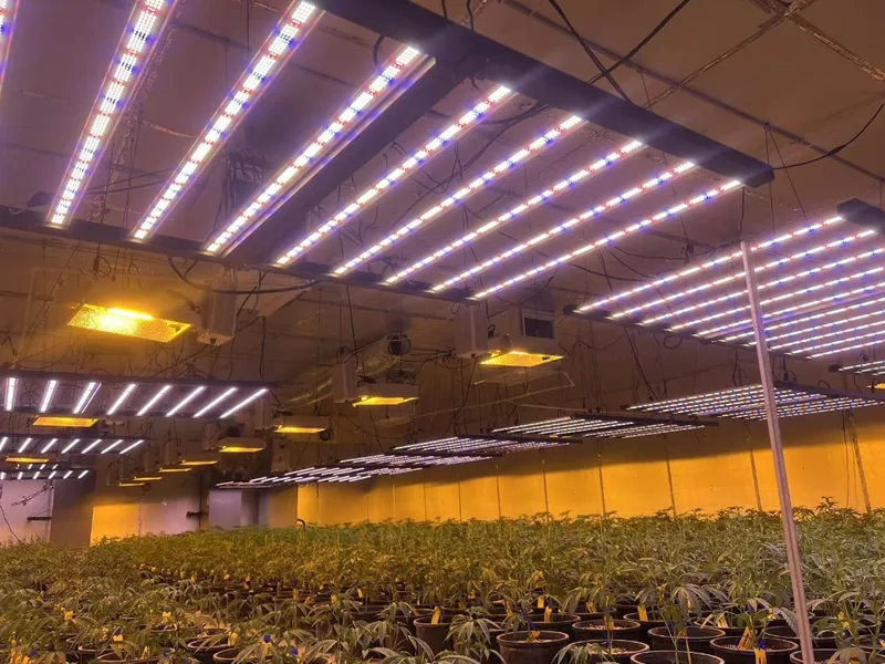
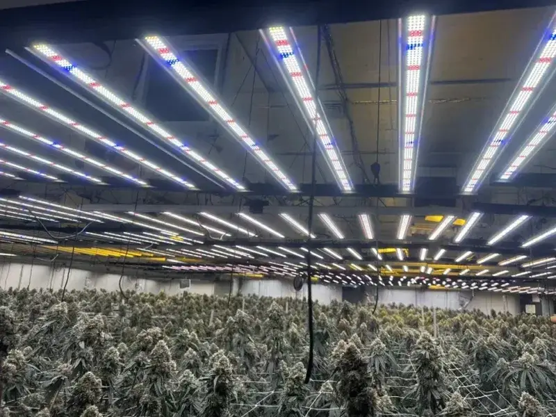
In a commercial indoor cultivation room, a grow light flickering fault isn’t just an annoyance—“LED grow light flickering” is a fault condition where light output is modulating (sometimes subtly, sometimes visibly) due to power, control, thermal, or component issues. It’s a fault condition where light output is modulating (sometimes subtly, sometimes visibly) due to power, control, thermal, or component issues. Left unresolved, it can introduce yield risk through inconsistent PPFD (photosynthetic photon flux density), create safety hazards during energized troubleshooting, and erode uptime—especially when symptoms are intermittent across zones or rooms.
This guide is written as an engineering-first workflow: isolate the root cause quickly, verify against standards-based measurements where possible, and close the loop with documentation so the fix is repeatable across sites.
Metrics worth tracking from the start (so you can compare “before” and “after”)—and to support LED driver flicker troubleshooting with evidence instead of guesswork:
- Pst/Plt: short-term and long-term flicker severity indices (commonly measured per IEC flicker methods).
- THD-V / THD-I: total harmonic distortion of voltage/current.
- PPFD uniformity: especially if flicker is zone-specific.
- Driver temperatures: case temperature and heat sink temperature.
- Power quality and switching context: sag/swell events, and whether the symptom looks like PWM-driven modulation vs AC-ripple behavior.
- Incident logs: timestamps, affected rows/zones, loads running, control mode, and any alarms.
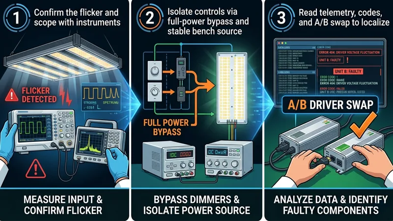
LED Grow Light Flickering Fault Troubleshooting Workflow
Confirm the Flicker and Scope with Instruments
Start by turning a complaint into a measurable signal.
- Confirm the symptom
- Use a light flicker meter if available. If not, a quick screening method is a slow-motion video to see whether modulation is present (useful for triage, not final verification).
- Note whether flicker is visible (low-frequency) or only detectable by the instrument (higher-frequency modulation).
2. Scope the blast radius
- Map the symptom: one fixture vs one row vs an entire control zone vs whole room.
- Look for correlations: only at low dim levels, only during HVAC compressor start, only when irrigation pumps run, only after lights have been on for 45–90 minutes (thermal).
3. Quick electrical sanity checks (before deep testing)
- Verify obvious mechanical/electrical issues: loose connectors, damaged cord grips, corrosion at plugs, loose neutral/ground terminations in accessible junctions.
- If flicker is widespread and coincident with other symptoms (fan speed changes, nuisance trips), treat it as a potential power quality event.
Done when: you can answer “where, when, and under what operating mode does flicker occur?” with timestamps and a zone map.
Isolate Controls Via Full-power Bypass and Stable Bench Source
Controls and power problems can look identical. The fastest way to reduce ambiguity is to remove variables.
- Bypass dimming/controls to force full output
- Temporarily run the affected fixtures at full power using the manufacturer-approved method (for example: disconnect 0–10V control lines and set to default full output, or use a known-good controller output).
- If flicker disappears at full power, you’ve narrowed the fault toward controls/wiring/low-dim behavior.
2. Use a stable source for A/B confirmation (when feasible)
- If you can safely test a suspect fixture/driver on a known-stable circuit (or bench source appropriate to your equipment), do it.
- The goal is not “lab perfection,” but a clean comparison: does the flicker follow the fixture/driver, or stay in the room?
Done when: you’ve separated “flicker caused by controls/dimming mode” from “flicker persists even at full-power.”
Read Telemetry, Codes, and A/B Swap to Localize
Once you’ve reduced variables, localize the failure to a component class.
- Read what the system is already telling you
- Pull driver/fixture telemetry if available: over-temperature flags, output current limit, undervoltage events, and runtime hours.
- Check controllers/gateways for fault codes, comms errors, dropped devices, or scene conflicts.
2. A/B swap in the smallest safe unit
- Swap one suspect driver/fixture with a known-good unit from the same environment.
- If the problem follows the hardware, you’ve got a component/thermal issue.
- If the problem stays with the location/circuit, you’re back to power quality, wiring, grounding, or controls.
3. Verify after every change
- After each swap or configuration change, re-measure (or at least re-confirm) flicker under the same operating conditions.
Done when: you can label the fault as primarily power quality, controls, thermal/environmental, or component degradation, with evidence.
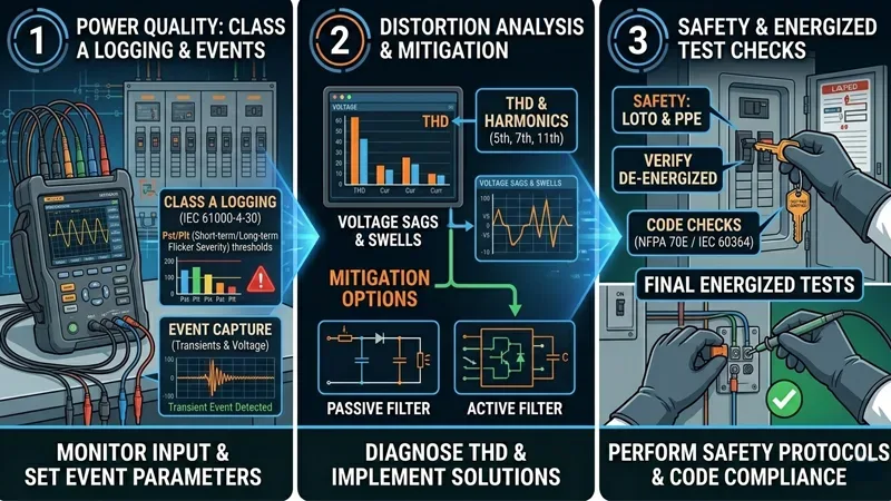
Power Quality and Measurement
Class A Logging, Pst/Plt thresholds, and Event Capture
In commercial facilities, intermittent flicker often tracks back to intermittent power events. That’s why “spot checking voltage” usually isn’t enough.
What thresholds should you use? Commonly referenced planning limits include Pst ≤ 1.0 and Plt ≤ 0.65, but your project should treat these as context-dependent targets rather than universal pass/fail values (utility requirements, contracts, and local norms vary).
Done when: you can pull a time-stamped log that shows whether flicker events coincide with voltage fluctuations, and you have Pst/Plt values to compare pre/post-fix.
THD/Harmonics, Sags/Swells, and Mitigation Options
Even when average voltage looks “fine,” waveform distortion and short events can still upset drivers—this is why power quality flickering lights Pst Plt THD data (captured consistently) is so useful during root-cause isolation.
What to look for:
- Sags/dips and swells: short drops or rises in RMS voltage that line up with motor starts, HVAC, irrigation pumps, or other cycling equipment.
- THD-V and THD-I: elevated harmonic distortion indicates nonlinear loads and can increase stress in power electronics.
How to correlate quickly:
Mitigation options (choose based on measured root cause, not guesswork):
- Circuit segregation: keep sensitive lighting circuits off the same feeders as heavy cycling loads.
- Line reactors / harmonic filters: where harmonics are measured and traced to specific equipment.
- Power conditioning / UPS (for controls/communications): when control-side stability is the weak link.
- Utility engagement: if upstream voltage regulation or service issues are suspected.
Done when: you can describe the disturbance class (sag/swell/harmonics) and show that mitigation reduced the event frequency/severity and stabilized light output.
Safety, LOTO, and Code Checks Before Energized Tests
Flicker troubleshooting tempts people into “quick checks” under load. Don’t skip safety.
- Use LOTO (lockout/tagout) before opening enclosures, moving drivers, or re-terminating conductors.
- Treat the room as a mixed-voltage environment: line voltage, low-voltage control, and in some cases, networked controls.
- When work must be energized, limit exposure: one change at a time, one circuit at a time, correct PPE, and an explicit test plan.
- If you suspect loose neutrals, shared neutrals, or panel issues, escalate to a qualified electrician—those faults can create broader hazards than lighting flicker.
⚠️ Warning: If your troubleshooting requires energized panel work, stop and involve a licensed electrician. The cost of downtime is real, but it’s never worth an injury or an arc-flash event.
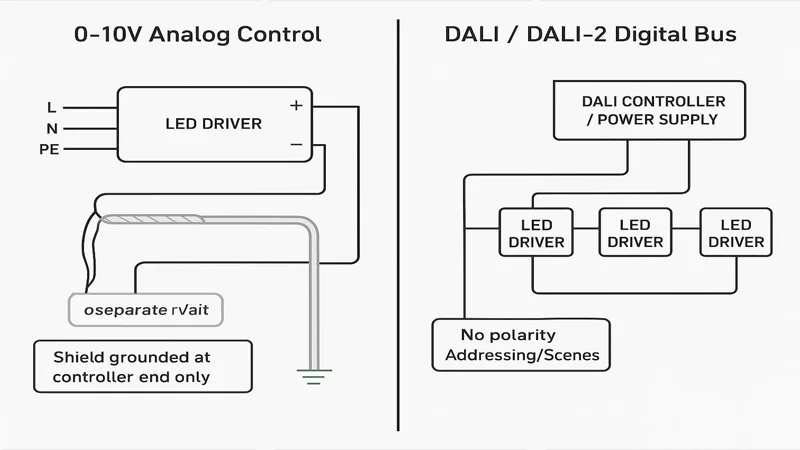
Controls: 0–10V and DALI/DALI-2
0–10V Diagnostics, Noise, and Source/Sink Compatibility
0–10V dimming is common in cultivation facilities because it’s simple—but it’s also easy to wire in a way that invites noise.
Start with the failure modes that most often create flicker:
- Polarity errors: a reversed +/– pair, or mixed polarity across fixtures in a daisy chain.
- Noise pickup: control wires run parallel to AC conductors, especially near VFDs (variable frequency drives), motor starters, or long cable trays.
- Grounding mistakes and loops: inconsistent references between the controller and drivers, or shields grounded at both ends.
- Source vs sink mismatch: ensure the controller output type matches the driver’s control input expectations.
Best-practice checks:
- Use shielded twisted pair for the 0–10V pair and maintain physical separation from line voltage conductors.
- Ground the shield at one end only (commonly the controller end) to reduce ground loops.
- Validate the control signal with a meter: you want a stable 0–10 VDC that doesn’t wander under load.
A practical wiring-focused checklist is outlined in Stars and Stripes Lighting’s 0–10V dimming flicker troubleshooting guide (2026).
If you need a quick refresher on control options and why they matter for automated cultivation strategies, SLTMAKS summarizes 0–10V and digital dimming approaches in an operations-friendly way.
Done when: flicker is eliminated at the same dim level after wiring/signal corrections, and the 0–10V signal remains stable during noisy load events.
DALI Addressing, Scenes, and Firmware Consistency
DALI (Digital Addressable Lighting Interface) and DALI-2 systems can reduce analog noise sensitivity, but they introduce a different class of issues behind DALI lighting flicker troubleshooting: configuration drift and interoperability.
Check these systematically:
- Addressing conflicts: two devices sharing an address, or devices intermittently dropping off the bus.
- Scenes and fades: unintended fade times or scene recalls that look like flicker.
- Firmware consistency: mixed firmware versions across drivers/controllers that handle dimming curves or limits differently.
Done when: affected devices maintain stable addressing/scene behavior and show no comms errors that correlate with flicker complaints.
BMS Gateways and Interoperability Considerations
In larger facilities, lighting controls often pass through gateways (BMS integrations, scheduling systems, environmental controllers). The flicker may not be in the driver—it may be in a control translation layer.
What to verify:
- Ensure gateways aren’t “chattering” setpoints (rapid, small dimming updates).
- Confirm update rates and smoothing logic.
- Validate fail-safe behavior: when comms drop, do fixtures hold last state, go to full power, or drop to a default?
Done when: the control command stream is stable (no rapid oscillation), and fail-safe behavior is understood and tested.
Thermal and Environmental Factors
OTP/OLC Behaviors and Visible Cycling Patterns
When flicker appears only after the room has been running for a while, treat thermal protection as a primary suspect.
Common pattern:
- Lights are stable at startup.
- After 30–90 minutes, output begins to modulate or step down.
- Cycling repeats as the system hits an internal temperature or current limit and then recovers.
This is often tied to OTP (over-temperature protection) or overload limiting behavior. Confirmation is straightforward: log driver case temperature and heat sink temperature over time, and correlate with the onset of flicker.
Done when: temperature data shows whether cycling aligns with protection thresholds.
Heat Sink Airflow, HVAC Interplay, and Canopy Microclimate
In cultivation rooms, the fixture isn’t operating in “free air.” It’s inside a coupled thermal system: rack geometry, ducting, dehumidification, and canopy transpiration.
Practical checks:
- Confirm airflow across heat sinks isn’t blocked by cable management, dust buildup, or retrofit baffles.
- Watch for HVAC modes that swing supply air temperature or velocity.
- Check whether canopy microclimate (humidity pockets) is creating localized corrosion/thermal insulation on heat sink fins.
Done when: airflow and ambient conditions are stable enough that the fixture reaches a steady thermal state without cycling.
Humidity, Corrosion, IP Ratings, and Connector Integrity
Humidity, nutrient aerosols, and cleaning processes can turn “fine on day one” wiring into intermittent faults.
- Inspect connectors for corrosion, compromised seals, and strain relief failures.
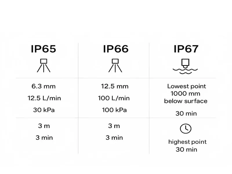
- Verify the fixture’s IP rating (Ingress Protection) matches the environment and cleaning method.
- If you’re seeing intermittent contact faults, address the connector systems and cable routing before replacing drivers.
A neutral note on vendor selection: in a commercial environment, reliability is often less about any single spec and more about consistent driver quality, thermal design margins, and certification discipline. SLTMAKS positions its commercial fixtures around reliable drivers and widely recognized certifications (such as ETL/CE/RoHS in its brand profile), which matters most when you’re trying to standardize across rooms and reduce “mystery faults” after retrofits.
For broader environmental considerations in vertical farms—especially around IP ratings and humidity—see SLTMAKS’s vertical farming LED lighting overview.
Done when: connectors, seals, and environmental fit are verified, and post-fix monitoring shows no recurrence tied to humidity/cleaning cycles.
Documentation, Standardization, and ROI
What to Log: IDs, Settings, Pst/Plt, THD, PPFD Before/After
If you want flicker fixes to scale, document like you’re building a maintenance standard—not like you’re putting out a one-off fire.
Log these items at a minimum:
- Fixture/driver IDs and locations (row/rack/zone)
- Control mode and settings (0–10V voltage, DALI scene/group, schedules)
- Pst/Plt (or whichever flicker metric you’re using consistently)
- THD-V / THD-I and any recorded sag/swell events
- PPFD map (before/after) for affected zones
- Driver/heatsink temperatures under steady-state
- Photos of wiring terminations and any rework
Done when: another technician can reproduce your test setup and understand the fix without re-interviewing you.
Preventive Maintenance and Standardized Components
Preventive work that pays off in commercial rooms is usually boring and repetitive:
- Standardize control topology (either clean 0–10V with disciplined wiring, or a digital bus with consistent commissioning).
- Standardize driver and connector SKUs where practical.
- Put scheduled inspections on the calendar: connector condition, cable strain relief, dust on heat sinks, and control cabinet grounding.
Done when: your site has a “known good” baseline that new installs and retrofits must match.
When to Escalate to Vendors or Certified Electricians
Escalate early when the symptom points outside normal fixture maintenance.
Escalate to a vendor when:
- Flicker follows a specific fixture/driver across A/B swaps.
- Telemetry shows recurring protection events under normal ambient conditions.
- Firmware/configuration inconsistencies can’t be reconciled with your commissioning tools.
Escalate to a certified electrician when:
- You suspect loose neutrals, panel/bus issues, or shared-neutral problems.
- Power quality logs show repeated sags/swells/harmonics that require electrical system redesign.
- Any troubleshooting step would require energized work beyond your site’s safe work practices.
Done when: ownership of the next action is clear, with evidence attached.
Conclusion
Commercial LED grow light flicker troubleshooting goes faster when you treat it as a closed-loop verification problem:
- confirm and scope with instruments, 2) bypass controls to reduce variables, 3) localize with telemetry and A/B swaps, then 4) verify stability with power quality logs and repeatable metrics.
If you’re measuring, focus on thresholds that indicate true stability—especially Pst/Plt for flicker severity and THD-V/THD-I plus sag/swell event capture for power quality—and document PPFD and thermal behavior so “fixed” really means fixed.
Next steps that usually reduce repeat incidents:
- Standardize your control topology (clean 0–10V wiring discipline or well-commissioned DALI) and validate fail-safe behavior.
- Make incident logging and periodic power quality snapshots part of preventive maintenance.
If you want, I can turn the logging section into a one-page, technician-ready “Flicker Incident Log Sheet” template you can standardize across rooms and sites.
FAQ
Why is my LED grow light flickering?
Most flicker comes from unstable input power (sags/swells), incompatible or noisy dimming/control signals (0–10V wiring noise, DALI scene issues), loose connections, or a driver hitting protection limits (over-temperature or current limiting).
Is LED grow light flicker bad for plants?
If flicker causes meaningful PPFD modulation or frequent output dips, it can reduce consistency and raise yield risk—especially in commercial rooms where uniformity matters. If the modulation is only detectable at very high frequency and PPFD stays stable, the practical impact is usually lower.
Why do LED grow lights flicker when dimmed?
Many drivers behave differently at low dim levels: control noise becomes a larger percentage of the signal, PWM/driver control loops can interact with long control runs, and some controllers “chatter” setpoints. Testing at full power (control bypass) is a fast way to confirm whether dimming is the trigger.
How do I stop LED grow lights from flickering in a commercial grow room?
Start by isolating whether it’s power or controls: run full power to bypass dimming, then A/B swap a known-good driver/fixture. If it’s controls, fix 0–10V polarity/shielding/separation (or DALI addressing/scenes). If it’s power quality, log events (Pst/Plt, THD, sag/swell) and mitigate with circuit segregation, filtering, or utility/electrical upgrades.