
The isolation barrier is the part of a grow light driver you cannot see, and it is the part that decides whether a fixture is safe to touch, safe to service, and safe to keep running in a wet, hot room. Guaranteeing true safety with a galvanic isolation grow light driver is not a single component choice. It is four separate engineering acts: designing the barrier, selecting the insulation class that barrier must meet, proving it with hipot testing, and documenting it inside a certificate whose scope actually covers the product you are buying.
This guide walks through each of those four acts in the order a manufacturer performs them, then turns them into a document-request checklist you can put in front of any supplier, including the ones already on your approved vendor list.
SLTMAKS is a global provider of professional-grade LED grow lights, engineering full-spectrum fixtures with advanced thermal management and international safety certifications including ETL, CE, and RoHS. Because the brand designs and certifies its own lighting hardware, its guidance on galvanic isolation in grow light power supplies comes from the same electrical safety and compliance work behind its products.
Table of Contents
What Galvanic Isolation Means in a Grow Light Driver
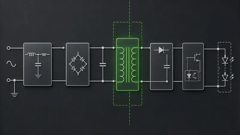
Galvanic isolation in a grow light driver means there is no direct conductive path between the mains-connected primary side and the LED output side; energy crosses the barrier only magnetically, optically, or capacitively. The barrier separates two circuits that share no copper.
Think of a moat rather than a wall. A wall stops movement by being solid. A moat stops movement by removing the path, while still letting supplies cross on a bridge you control. Isolation works the same way: the transformer, optocoupler, or capacitor is the bridge, and everything about its construction decides what may cross.
That distinction matters more in a grow room than in a typical fixture. High ambient temperature ages insulation, condensation inside an IP-rated enclosure can bridge a marginal gap, and multi-fixture installations create ground loops between drivers that share a control bus. Each condition attacks the barrier rather than the electronics.
The payoff is on the output side. Because the secondary is separated from mains, the LED side can be made touchable and a Class 2 or SELV claim becomes possible at all. That claim rests on the barrier holding, which is why the insulation classes that safety standards distinguish are worth naming precisely rather than treating “isolated” as a single condition.
Isolated vs Non-Isolated: The Trade-Off You Are Actually Choosing
The isolated vs non-isolated LED driver decision is really a decision about where the insulation burden sits. In an isolated design (flyback, forward, half-bridge, LLC), a transformer inside the driver carries the barrier, so the output can reach SELV or Class 2 and stays touch-safe. In a non-isolated design (buck, boost, buck-boost), the driver holds no barrier at all: the output is not touch-safe, and the insulation has to come from the luminaire and the grounding.
That difference has a price. According to one driver vendor’s own comparison of isolated and non-isolated designs, published in April 2025, non-isolated drivers run roughly 25% lower in cost with higher efficiency and a smaller footprint, while isolated equivalents are listed at about 25% higher cost with mid-range efficiency. Treat that as a single vendor’s estimate, not a corroborated benchmark, and note that uPowerTek sells both topologies, so the framing is not neutral by default.
| Criterion | Isolated | Non-isolated |
|---|---|---|
| Output safety | Relatively safe; SELV or Class 2 achievable | Not touch-safe |
| Cost | ~25% higher (vendor estimate) | ~25% lower (vendor estimate) |
| Efficiency | Mid (vendor estimate) | Higher (vendor estimate) |
| Size | Larger | Smaller |
| Dimming interfaces | 0–10V, PWM, DALI-2 | 0–10V, PWM (control-side isolation still required) |
| Insulation burden | Inside the driver | Luminaire and grounding |
Non-isolated is not automatically the wrong choice. It shifts the insulation burden to the luminaire and the grounding, which is a legitimate trade-off when the enclosure and earthing are under your control.
The Insulation Classes Behind the “Isolated” Label
“Isolated” tells you the topology. It does not tell you which insulation class the barrier achieves, and that distinction decides whether the output is safe to touch.
The vocabulary builds in layers. Functional insulation is required only for the circuit to work and is not a shock safeguard. Basic insulation provides one level of protection against electric shock. Supplementary insulation is a second, independent layer added to basic insulation. Double insulation combines the two. Reinforced insulation is a single system rated to the same performance as double insulation.
For a mains-to-SELV output, that level matters. Why a mains-to-SELV output needs more than basic insulation is straightforward: the barrier between mains and a user-accessible SELV output must be reinforced or double insulation. Basic insulation alone is generally insufficient unless protective earthing is part of the overall design. The TI overview is undated; the IEC 62368-1 sample it draws on is Edition 4.0, dated May 2023.
Protection class frames the same requirement from the installation side. What separates Class I, Class II and Class III construction comes down to where the safety ground sits. Class I uses insulation plus protective earthing, and a safety ground is mandatory. Class II uses two levels of insulation, double or reinforced, with no earthing and no protective-earth conductor required. Class III is fed from a SELV source and needs no further protection.
Key Takeaway: “Isolated” on a spec sheet is a topology description, not an insulation-class claim.
So what does this mean when you specify a galvanic isolation grow light driver? You cannot confirm the class from a datasheet bullet. Only the supplier’s construction file shows which insulation class the barrier actually achieves.
Designing the Barrier: Creepage, Clearance and Pollution Degree
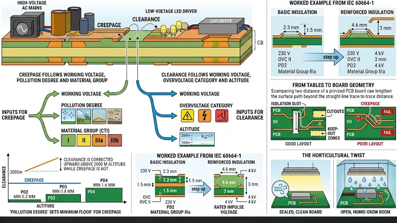
The isolation barrier in a grow light driver is a set of measured distances on the PCB, not a component you can point to. Two distances govern whether the design passes: creepage and clearance. Creepage is the shortest path along the insulating surface between two conductive parts; clearance is the shortest path through air. Creepage and clearance in an LED driver are set by different inputs, which is why a single generic table cannot answer the question.
Creepage follows working voltage, pollution degree, and material group (CTI I, II, IIIa, IIIb). Clearance follows working voltage, overvoltage category and altitude. How pollution degree and material group drive creepage sets out the full input list.
The numbers are concrete. At 230 V mains with basic insulation, OVC II, pollution degree 2 and material group IIIa, a worked IEC 60664-1 example with the numbers shown gives a rated impulse voltage of 2.5 kV, clearance of 1.5 mm and creepage of 2.3 mm. Step up to reinforced insulation and the impulse rises to 4 kV, clearance to 3 mm and creepage to 4.6 mm.
Two structural rules catch people out. Required creepage can never be less than required clearance, and clearance is corrected upward above 2000 m altitude while creepage is not, because creepage is a surface phenomenon. Pollution degree also sets floors: PD2 at least 0.2 mm, PD3 at least 0.8 mm, PD4 at least 1.6 mm.
Layout is where the tables become geometry. How designers work backward from the standard’s tables to board geometry is the practice of identifying the barrier first, then checking clearance for the transient case and creepage for the working voltage. Isolation slots, cutouts, and keep-out zones lengthen the surface path beyond the straight-line trace-to-trace distance.
The horticultural twist most spec sheets miss: a sealed, clean board lowers the pollution degree and can reduce required creepage. An open, humid grow room pushes it up fast.
Verifying the Barrier: Hipot Type Test vs Routine Test
A hipot pass means nothing until you know which test was run, at what voltage, for how long, and on how many units. That is the core of driver isolation testing hipot: the paperwork looks identical whether a design was qualified once or every unit was screened.
The two tests differ in kind. A type test runs for 60 seconds and qualifies the design; a routine test runs for 1 second at the same voltage and screens every production unit. IEC 60335-1 Annex A permits a 5-second routine alternative with the appliance at operating temperature (Regulatory Decoded, retrieved 2026-05-25).
Voltage follows insulation class, not a formula. At roughly 325 V peak working voltage (230 V AC mains), expect about 1500 V AC for basic insulation and about 3000 V AC for reinforced. IEC 62368-1 keys the dielectric-strength test voltages keyed to insulation class in Table 15, replacing the withdrawn 2U+1000 V calculation.
Test points matter too. Reinforced isolation is proven input-to-output; basic isolation is proven input-to-chassis, with accessible parts tied together. Which points the hipot probe actually touches determines what the record proves.
Key Takeaway: Before accepting a hipot record, ask in writing for the test voltage, duration, test points, and leakage-current limit. Without a stated limit, pass/fail becomes subjective rather than a measurement.
What the Certificate Actually Covers
A UL mark, an ETL mark, and a CE declaration are not interchangeable, and a test report is not a certification. Grow light power supply safety certification runs through the federal program behind the UL and ETL marks on a driver label: the OSHA Nationally Recognized Testing Laboratory Program recognizes private organizations to certify products against OSHA electrical standards. Each NRTL is recognized for a defined scope of test standards and uses its own registered mark, which signifies the product was tested and complies with one or more product safety standards.
That mechanism explains why a CE declaration and a UL listing are not the same document. UL and ETL are functionally equivalent OSHA-recognized NRTLs, while CE is a manufacturer self-declaration with no issuing authority, and a test report alone is not a certification (Compare2Best lighting certification guide, 2026-07-10). The distinction tells you which mark proves safety and which only proves performance: DLC certifies efficacy through a qualified products list, not electrical safety, while UL 1598 and UL 8750 carry the North American safety scope.
UL 8750 covers LED drivers but supplements the luminaire standard rather than replacing it, and it is not harmonized with IEC/EN 61347-2-13, so compliance with one does not imply the other (KSimpexp LED certification guide, undated). That is how the driver standard and the luminaire standard fit together: the fixture and its LED components are each evaluated.
| Document | What it proves | What it does not prove |
|---|---|---|
| UL / ETL listing | Product tested by an OSHA-recognized NRTL against a named safety standard | That the specific SKU you ordered is inside the listed family |
| CE Declaration of Conformity | Manufacturer’s own declaration of conformity | Independent third-party testing or an issuing authority |
| Test report | Results of the tests performed | Certification, or that a listing exists |
| DLC listing | Performance and efficacy qualification | Electrical safety or isolation |
What a certificate’s scope actually lets you verify is narrower than the mark suggests: it should let you match the certificate to the listing record by file number, identify the standard and its edition, and confirm your SKU sits inside the covered family. For procurement, the essential set is that scoped NRTL certificate, routine hipot test evidence, a creepage and clearance compliance statement, and the insulation-system datasheet. LM-79 reports are photometric evidence, not proof of electrical isolation, and RoHS or REACH declarations are environmental, not safety documents.
One caveat on factory-inspection cadence and annual cost figures you may see quoted for maintaining a listing: those numbers circulate without a stated methodology, so treat them as advisory only and confirm the current cadence with the NRTL or your supplier.
Common Mistakes When Specifying an Isolated Driver
The most expensive mistakes in this category are documentation mistakes, not engineering ones. Each one below is a gap between what a buyer assumes a document proves and what it actually proves.
Accepting “isolated” as an insulation-class claim. The word describes a topology, not a barrier rating. Why it happens: datasheets lead with “isolated” because it sells. The fix: ask which insulation class the barrier is built to, and where that class is stated in the certificate scope.
Accepting a hipot record with no stated voltage, duration, or leakage limit. A pass mark without test conditions cannot be reproduced or compared across suppliers. Why it happens: routine-test sheets are formatted for production, not for procurement. The fix: require all three parameters on the record before you file it.
Treating a CE mark or a test report as equivalent to an NRTL listing. A self-declaration and an accredited listing are different instruments with different scopes. The fix: confirm which body issued what, and for which product family.
Specifying creepage from a generic table without stating pollution degree, material group, and altitude. The table value is only valid under those conditions. The fix: put the three conditions in the specification itself.
Mixing driver brands in one facility without checking barrier compatibility. Each barrier has its own reference and grounding scheme. The fix: verify the schemes agree before the fleet grows.
Key Takeaway: Send any supplier this five-item request: (1) insulation class of the barrier and where it appears in the certificate scope; (2) hipot routine-test record stating voltage, duration and leakage limit; (3) NRTL listing number and the product family it covers; (4) creepage and clearance figures with pollution degree, material group and altitude stated; (5) barrier reference and grounding scheme, for mixed-fleet compatibility checks.
Get those five documents before you specify a galvanic isolation grow light driver into a facility, and most of the risk in this section disappears at the paperwork stage rather than at the installation stage.
Conclusion
You can now read an isolation claim as a set of verifiable documents rather than a label: certificate scope, creepage and clearance figures, and hipot test records that either support the claim or do not. The clearest way to hold a supplier to that standard is the reinforced-versus-basic relationship, where reinforced insulation requires roughly double the creepage distance of basic insulation at the same working voltage (4.6 mm against 2.3 mm) and is type-tested at about twice the hipot voltage (≈3000 V AC against ≈1500 V AC). Ask for those two numbers together, because one without the other proves little about a galvanic isolation grow light driver.
If the documentation set you receive does not answer those questions, SLTMAKS can be used to walk through the specific clauses and test records that apply to your installation. Talk to an expert or request the compliance document set before you place the order.
FAQ
What is the difference between an isolated and a non-isolated LED driver?
An isolated driver uses a transformer or optocoupler to separate the mains input from the LED output, so the two circuits share no direct conductive path. A non-isolated driver connects input and output more directly, with no galvanic barrier at all. In practice, isolated designs buy a larger safety margin and better surge tolerance but are usually heavier, larger, and more expensive, while non-isolated designs are smaller and cheaper but push the insulation burden onto the enclosure and grounding. For high-power, humid, or safety-critical grow installations, isolated is the safer default (BATA’s grow light driver comparison and theOneGrow’s isolated vs non-isolated guide).
What hipot voltage should a reinforced-isolation driver pass?
What hipot voltage should a reinforced-isolation driver pass?
For equipment rated up to 250 V, reinforced insulation is typically tested at 3000 V AC, roughly double the 1500 V AC used for basic insulation at the same working voltage. Translated to DC, 3000 V AC is about 4242 V DC. Medical-device contexts push this higher to 4000 V AC, but for grow light drivers the reinforced figure of 3000 V AC is the one to expect. A common rule of thumb is two times the working voltage plus 1000 V, but the insulation class in the product standard governs the final number (Regulatory Decoded’s hipot guide and Micom Labs’ hipot testing reference).
Does a CE mark prove a driver is galvanically isolated?
Does a CE mark prove a driver is galvanically isolated?
No. CE is a manufacturer’s self-declaration of conformity and has no issuing authority behind it, so it does not prove independent testing or a specific isolation class. In North America, the comparable proof is a listing from an OSHA-recognized National Recognized Testing Laboratory, such as UL or ETL, which certifies the product against a named safety standard (OSHA’s NRTL Program). The two are different instruments with different scopes, so a CE declaration alone tells you little about the barrier inside the driver (Compare2Best lighting certification guide).
How do I check whether a certificate covers the exact driver I ordered?
Match three things, not just the mark. First, match the certificate to the listing record by file number so you know the record is genuine and current. Second, identify the safety standard and its edition, since a listing to an older edition may not reflect today’s requirements. Third, confirm your specific SKU sits inside the listed product family, because a listed family can span several models and a mark on the label does not guarantee every variant inside it was evaluated. If the supplier cannot produce a scoped certificate that names your model, treat the isolation claim as unverified.