Introduction
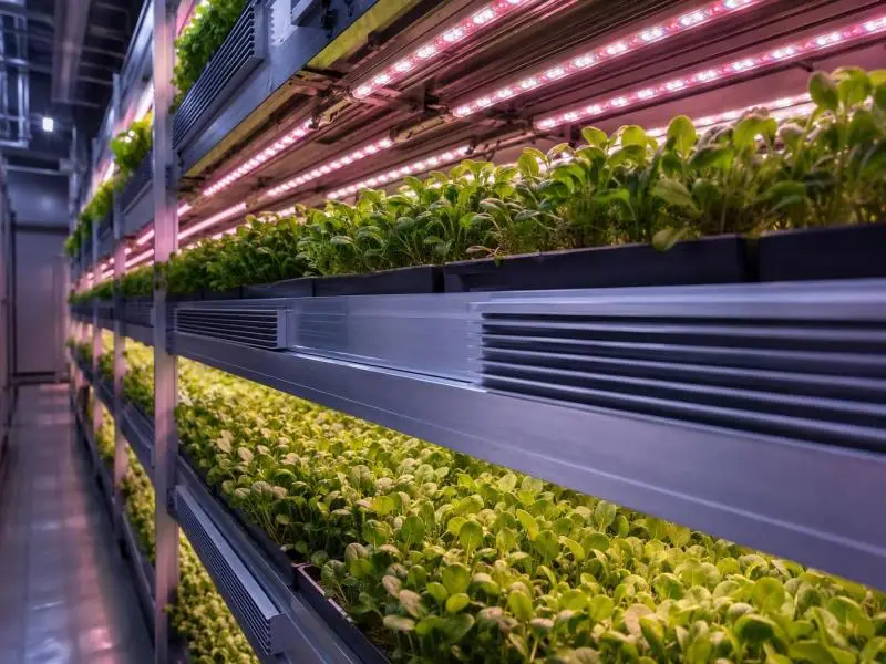
An LED driver in a commercial indoor farm sits at the intersection of two hostile conditions. The first is the grow environment itself: high transpiration rates, frequent fogging and misting, and relative humidity that can sit near saturation for long stretches of a photoperiod. The second is cleaning. Between cycles, many facilities wash down benches, gutters, trays, and light fixtures with spray or jets, and the driver housing takes the splash even when the fixture is rated for it.
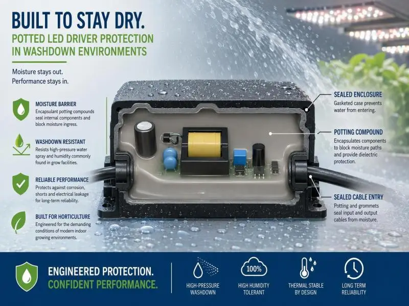
Potting addresses both. By utilizing advanced potting compounds for LED drivers, they are thoroughly protected; filling the driver cavity with a cured resin embeds the PCB, magnetics, connectors, and solder joints in a solid or elastomeric medium, so moisture has to diffuse through the compound rather than condense directly on biased conductors. That changes the failure physics: surface insulation resistance stops being a function of what is growing on the board, and the assembly gains mechanical support against vibration and thermal cycling.
This article gives you the criteria to specify potting with confidence: how moisture actually damages drivers, how epoxy, polyurethane, and silicone differ on barrier performance and stress, which IP and environmental tests to require, and how to model the reliability gain against downtime and total cost of ownership. SLTMAKS builds horticultural luminaires around these same thermal and sealing constraints, so the examples below stay close to what a cultivation operator will actually see in a submittal package.
Table of Contents
Evaluating Potting Compounds: LED Drivers and Humidity Risks
How Moisture Causes Electrical Leakage and Corrosion
Water alone is not the main problem. The problem is water plus ionic contamination plus a voltage difference. When a thin film of moisture forms on a PCB surface, it dissolves flux residue, salts, and other contaminants into a conductive electrolyte. That film bridges adjacent tracks at different potentials and creates micro-electrochemical cells. Surface insulation resistance falls, leakage current rises, and if the film persists, metal dissolves at the anode and plates back out as dendrites that eventually short the gap.
A 2026 study published in Surfaces and Interfaces tracked this process on biased boards under controlled condensation and found that droplet coalescence into a continuous water film, rather than the presence of isolated droplets, was the limiting factor for failure; electrochemical processes accelerated once a continuous film bridged the conductors (DTU Orbit record). The practical implication for a driver is that intermittent condensation is not automatically benign. Repeated wet-dry cycles can build up corrosion products and dendrite precursors until one cycle completes the bridge.
Corrosion follows the same logic. Copper tracks, solder joints, and component terminations oxidize and, under bias, corrode electrolytically. Sulfur-bearing atmospheres add another pathway, attacking copper and silver. Potting interrupts the sequence by keeping the electrolyte off the surface in the first place.
Failure Modes Seen in Humid Grow Environments
The failures that show up in humid cultivation facilities tend to cluster into a few recognizable patterns:
- Insulation resistance drift. Drivers pass incoming inspection, then fail a hipot or insulation-resistance check at the next maintenance window. The board looks clean but leakage has crept up across a contaminated surface.
- Dendritic shorts on fine-pitch areas. Controller pins, optocoupler leads, and connector tails are the usual sites. Failures often appear as intermittent flicker or dimming faults before becoming hard shorts.
- Electrolytic corrosion at connectors and terminals. Moisture wicks into crimped or screw terminals, and the resulting resistance rise causes local heating and, in the worst case, arcing.
- Delamination and cracking of protective layers. A coating that did not adhere properly, or a potting compound that shrinks hard against a component, can open a path for moisture rather than block it.
- Condensation on cold surfaces during lights-off. In a warm, humid room, a fixture that cools after the photoperiod can drop below the dew point. Condensation inside an enclosure that breathes is a common route to the failures above.
Layered Protection Strategy: Enclosure, Seals, Coatings, Potting
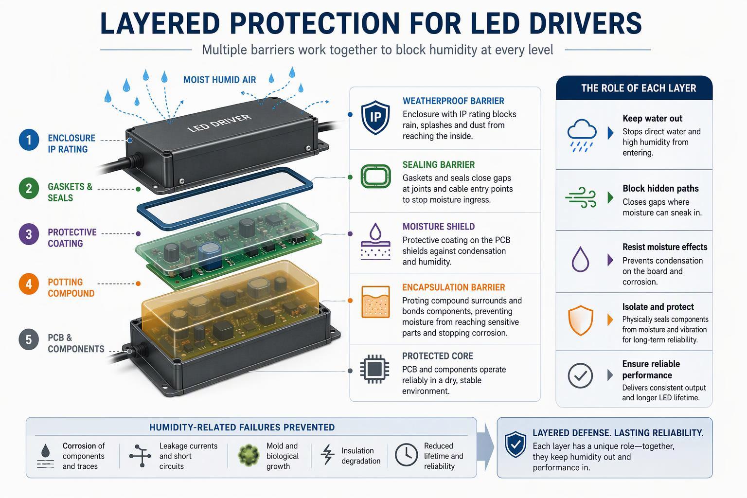
No single layer carries the whole job. A defensible design uses four layers, each doing a distinct task:
- Enclosure and IP rating. The housing keeps bulk water out and defines the tested ingress level. It does not stop vapor diffusion through gaskets and cable entries over time.
- Gaskets and seals. These close the mechanical interfaces: lid joints, cable glands, connector faces. They are the first thing to degrade under repeated washdown and thermal cycling, so they need a replacement interval in the maintenance plan.
- Conformal coating. A thin polymer film on the PCB slows surface moisture and contamination. It is compatible with rework and inspection, but it is thin, and it does not fill around component bodies or provide mechanical support.
- Potting. A filled resin embeds the assembly, providing the thickest barrier and mechanical coupling. It is the layer that makes the difference in high-humidity, washdown-exposed installations, and it is also the least reversible.
The layers are complementary, not alternatives. A potted driver in a poorly sealed housing still sees water at the cable entry; a well-sealed housing around an uncoated, unpotted board still accumulates condensed moisture inside. Specify all four and test the combination.
Potting Materials Compared
Epoxy vs Polyurethane vs Silicone: Moisture Barrier and Dielectric
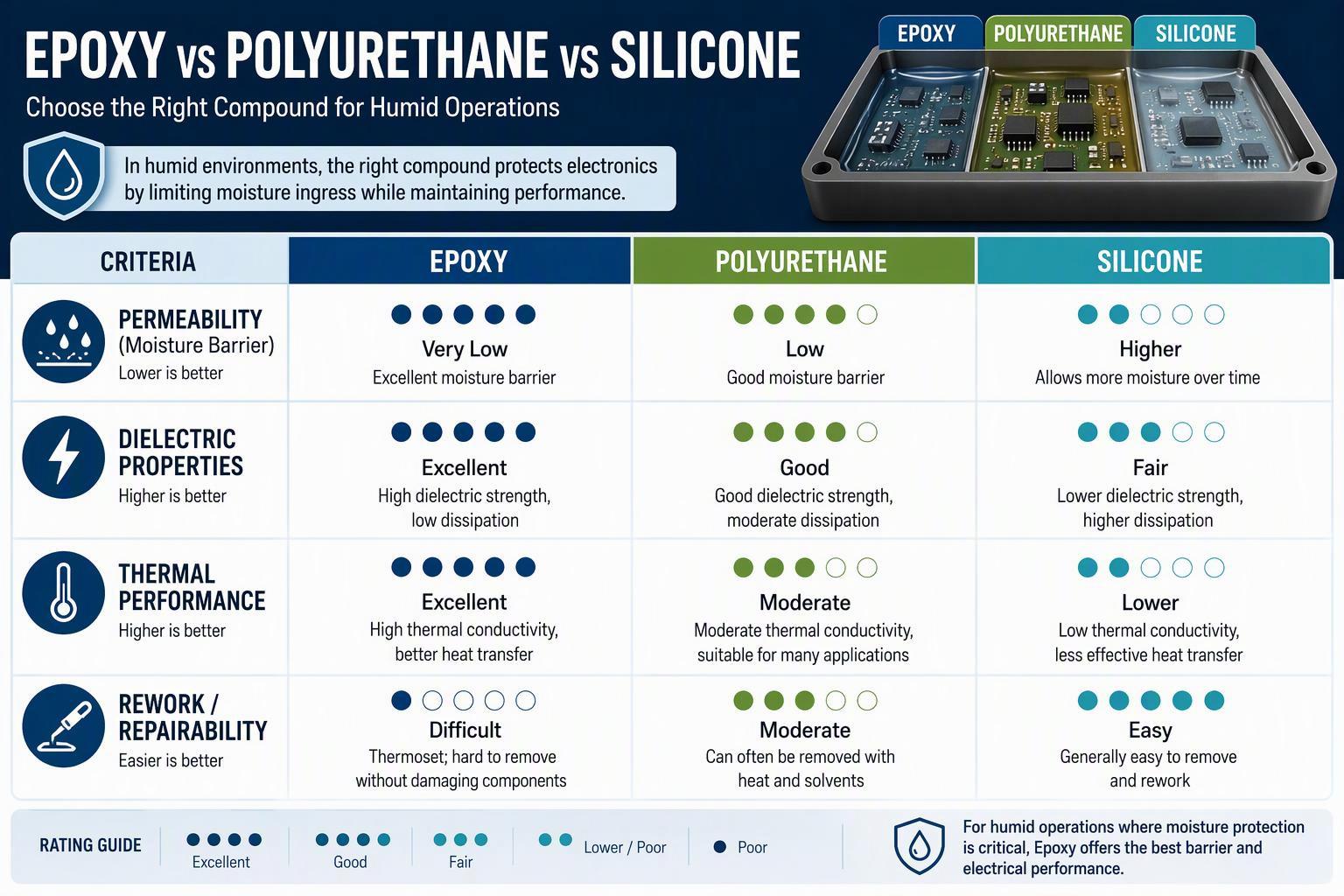
All three chemistries are used in LED driver potting, and all three can be formulated to meet electrical safety requirements. The key differences are water uptake, hardness, and how the cured material behaves under stress.
Epoxy is the hardest and most dimensionally stable of the three. It bonds strongly to the housing and components, provides good mechanical support, and is widely used where the driver is sealed for life. Its weakness is rigidity: a hard cure transmits thermal expansion mismatch directly to solder joints and component bodies. Water absorption varies by formulation.
In a published WEVO lighting potting table, epoxy and polyurethane products show 30-day water absorption in roughly the 0.3–1.5% range, while a silicone gel in the same table is listed as not applicable for that measurement (WEVO lighting brochure). Treat those figures as formulation-specific, not as a ranking of chemistries.
Polyurethane sits between epoxy and silicone. It is tougher and more flexible than epoxy, tolerates thermal cycling better, and is commonly used in drivers that see wide temperature swings. It adheres well to most housings and offers good dielectric performance. Its limitations are moisture sensitivity during cure and a narrower high-temperature ceiling than epoxy in many formulations.
Silicone is the most flexible and the most thermally stable across a wide range. It places the least stress on components during cure and cycling, which makes it attractive for large magnetics and delicate joints. The trade-offs are mechanical: silicone is soft, provides less structural support, and can outgas after cure. RECOM notes that automotive applications exclude silicone potting because the compound can still outgas after cure and form a film on adjacent surfaces, while railway applications do not accept it because in a fire it could release smoke that could cause panic in an enclosed space; the requirements of both can be addressed with epoxy or polyurethane alternatives instead (RECOM potting guide).
For a sealed horticultural driver, outgassing is less of a concern than for painted automotive parts, but it still matters if the driver shares an airspace with optics.
On dielectric performance, all three families are routinely formulated well above the field strengths a driver will see. The relevant question is not which chemistry has the highest breakdown voltage on a datasheet, but whether the cured compound, at the specified thickness, maintains insulation resistance and withstand voltage after humidity conditioning. That is a test question, not a chemistry question.
Thermal Behavior and Mechanical Stress under Cycling
A driver in a grow room cycles every photoperiod. The compound expands and contracts with the board, the magnetics, and the housing, and each material has a different coefficient of thermal expansion (CTE). The stress that develops at those interfaces is what cracks solder joints, opens gaps at the housing wall, and delaminates the compound from component bodies.
Two properties govern the outcome. The first is CTE: a compound with a CTE close to that of the PCB and copper reduces the mismatch. The second is modulus, or hardness. A softer cured compound distributes the strain elastically instead of transmitting it to the joint. RECOM’s guidance is direct on this point: use compounds that retain some softness after cure so that shrinkage stress is dissipated, and prefer low-CTE formulations so thermal cycling does not load the components (RECOM).
Thermal conductivity is the third variable. A driver dissipates heat through its housing, and the potting compound is part of that path. Thermal conductivity values of roughly 0.2 to 3 W/m·K appear across the potting compounds listed in a commercial lighting potting table (WEVO). For a driver with a hot transformer or a dense cluster of switching devices, thermal conductivity is worth specifying explicitly rather than assuming.
Serviceability and Rework Trade-offs for Maintenance
Potting is close to irreversible. Removing cured epoxy from a board without damaging it is impractical for most systems, and even soft silicones are difficult to excavate cleanly. That has two consequences for a cultivation operation.
First, the board must be proven good before it is potted. Trapped flux residue under the compound is a corrosion site that cannot be cleaned afterward, so cleanliness verification, inspection and functional test all have to happen upstream. PCBCart’s selection framework makes the same point: potting removes the rework option, so pre-pot inspection and process records carry the quality burden (PCBCart).
Second, the maintenance strategy shifts from repair to replacement. A potted driver that fails is a swap-out, not a bench repair. That is acceptable when the driver is designed as a field-replaceable module with accessible connectors, and it is a problem when the driver is buried inside a fixture that requires a lift and two technicians to reach. For multi-tier vertical racks, the labor cost of a swap is a real line item in the TCO model, and it argues for specifying drivers that can be replaced at the fixture level without disturbing the canopy.
Where rework is a hard requirement, conformal coating plus a sealed housing is the more compatible choice. Potting and coating are not interchangeable; they answer different questions.
Compliance and Testing Framework
Selecting IP Ratings (IP65–IP67) for Washdown Zones
The IP code is defined in IEC 60529, which classifies enclosure protection against solid objects (first digit) and water (second digit) (Castle Compliance summary). For horticultural drivers, the second digit is where the decision lives.
- IP65 covers water jets from a 6.3 mm nozzle at 12.5 l/min for at least three minutes. It suits overhead spray, misting systems and low-pressure washdown.
- IP66 covers powerful jets from a 12.5 mm nozzle at 100 l/min. It is the right target for direct hose-down of fixtures and gutters.
- IP67 adds temporary immersion for 30 minutes at defined depths. It matters where fixtures sit in low trays, on floors that flood during cleaning, or in rooms where runoff pools on surfaces.
Two practical points. First, within the spray tests, a higher water rating satisfies the lower ones, so IP66 covers IP65 spray; but spray and immersion are separate tests, and a product that must survive both needs a dual rating such as IP66/IP67. Second, the IP rating applies to the enclosure as tested, with the cable entries and gaskets in their specified condition. A gasket that has been opened for service and not reseated correctly is no longer an IP66 enclosure, which is why the maintenance procedure matters as much as the rating.
Match the rating to the zone, not to the whole facility. A driver mounted above the canopy in a fogging room may only need IP65; a driver at bench height in a washdown bay may need IP66/IP67. Specifying IP67 everywhere adds cost without adding protection where it is not needed.
Environmental Validation: 85/85, Damp Heat Cyclic, Condensation, Spray
IP testing covers liquid water. It does not cover the vapor-and-condensation cycle that dominates a grow room, so environmental validation has to be specified separately.
Damp heat, steady state (85/85). The common industry shorthand for 85 °C and 85% relative humidity, run for a defined duration. It is the standard screen for moisture-driven insulation degradation and is widely used for coating and potting qualification. The IEC equivalent for steady-state damp heat is Test Cab in IEC 60068-2-78, which holds 40 °C or 55 °C at 93% RH for four to fifty-six days; 85/85 is a harsher in-house variant that many suppliers run in addition (Payapress IEC 60068 overview).
Damp heat, cyclic (IEC 60068-2-30, Test Db). This test cycles between 25 °C and an upper temperature, with relative humidity above 95% during the warm phase, over a 24-hour cycle. The purpose is to reproduce dew formation and condensation, which is exactly the mechanism a grow room produces when lights go off and surfaces cool (IEC 60068-2-30:2005; Intertek summary). A potting qualification that only runs steady-state 85/85 can miss condensation-driven failures; it requires the cyclic test as well.
Condensation-specific testing. Some suppliers run dedicated condensing-humidity tests or powered condensation cycles that bias the board while dew forms. These are closer to the field condition than either steady-state or cyclic damp heat alone, and they are worth asking for when the driver will be installed in a fogging or misting zone.
Spray and jet testing. Covered by the IPX5/IPX6 tests above. Require the test report, not just the rating claim, and check that the test was run with the production gasket and cable entry configuration.
A validation matrix for a horticultural driver typically combines: IPX5 or IPX6 spray, IEC 60068-2-30 cyclic damp heat, a steady-state 85/85 run of defined duration, and a powered condensation test. The durations should be set against the expected service life and the maintenance interval, not copied from a generic datasheet.
Electrical Safety: Creepage/Clearance, Insulation Resistance, Dielectric Withstand
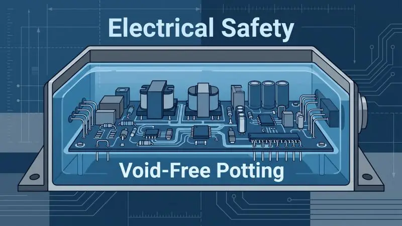
Potting is part of the safety architecture, not just a moisture barrier. IEC 61347-2-13, the particular safety standard for LED controlgear, requires that SELV controlgear comply with insulation resistance, electric strength, and creepage and clearance requirements between primary and secondary circuits (IEC 61347-2-13:2014).
Three implications for potting:
- Creepage and clearance are measured through and over the compound. A potted assembly can meet spacing requirements that an air-insulated design cannot, but only if the compound is qualified as an insulating material and the production process controls voids. A void in the wrong place is an air gap in the safety barrier.
- Insulation resistance must hold after humidity conditioning. A driver that passes IR at incoming inspection and fails after damp heat has a moisture path, and the potting or the process is the place to look.
- Dielectric withstand is a production and a type test. The type test proves the design; the production hipot proves the unit. Potting process control, including void-free fill, is what makes the production test meaningful.
For North American projects, UL 8750 defines dry, damp and wet location categories, and the driver’s location classification drives which requirements apply (Lisun comparison of UL 8750 and EN 61347-2-13). Confirm the location classification with the authority having jurisdiction (AHJ) before finalizing the enclosure and potting specification, because a wet-location classification can change both.
Selection, Application, and ROI
A Practical Checklist for Specifying Potting in LED Drivers
Use this list as the specification skeleton for a submittal or a supplier qualification:
- Define the exposure zone. Overhead fogging, bench-level washdown, or floor-level flooding. Map each zone to an IP target (IP65, IP66, IP66/IP67) and to a condensation test requirement.
- State the chemistry and the reason. Epoxy for rigid, sealed-for-life drivers; polyurethane where thermal cycling dominates; silicone where component stress is the primary concern. Require the supplier to justify the choice against the cycling profile.
- Specify thermal conductivity and CTE. Give a target range for thermal conductivity based on the driver’s dissipation, and require a CTE that is compatible with the PCB and magnetics.
- Require void-free process control. Vacuum mixing and vacuum dispensing, with sectioning or X-ray monitoring as evidence. A void-free claim without process evidence is not a specification.
- Set the validation matrix. IPX5/IPX6 spray, IEC 60068-2-30 cyclic damp heat, steady-state 85/85, and a powered condensation test, each with a defined duration and pass criterion.
- Require the safety file. Insulation resistance, dielectric withstand and creepage/clearance evidence against IEC 61347-2-13 or UL 8750, as applicable to the destination market.
- Confirm serviceability. Driver replaceable at fixture level, connector access, and a documented gasket reseating procedure.
- Tie the spectrum and thermal design to the driver envelope. A fixture whose optical and thermal design pushes the driver harder needs a potting specification that reflects the higher case temperature. SLTMAKS publishes spectrum and thermal data for its horticultural fixtures so that the driver envelope can be checked against the intended duty cycle.
Application Best Practices: Cleanliness, Degassing, Staged fills
Potting quality is a process outcome. The compound datasheet describes the cured material; the process determines whether the cured material in the housing matches the datasheet.
Cleanliness before fill. Flux residue, handling oils, and dust are corrosion sites sealed under the compound. The board should be cleaned and verified clean before potting, and the housing interior should be free of mold release agents and particulates. Contamination is one of the most avoidable causes of potting defects, affecting adhesion and wetting.
Degassing. Mixing introduces air. Vacuum mixing removes it before dispensing, and vacuum dispensing prevents re-entrainment. RECOM describes vacuum mixing and dispensing as the most effective technique for eliminating significant air inclusions, and notes that in some power supplies the potting is part of the approved safety isolation barrier, with void-free performance controlled in production and verified by sectioning or X-ray (RECOM).
Staged fills. Deep cavities filled in a single pass trap air and can leave incomplete flow around tall components. Staged potting lets each layer settle and release air before the next is added (ANZER). The number of stages and the settle time depend on the compound viscosity and the geometry, and they belong in the process documentation, not in the operator’s judgment.
Cure control. Exotherm, cure temperature, and cure time all affect shrinkage and stress. A compound cured too fast in a thick section can develop internal voids or crack. Follow the datasheet cure schedule and verify it with a sample section from each production lot.
Quantifying Reliability Gains, Downtime Avoidance, and Total Cost of Ownership
The ROI case for potting rests on three numbers: the failure rate without it, the cost of a failure, and the cost of potting.
The failure rate is the hardest to pin down, and it should come from your own fleet data or from a supplier’s field return data, not from a generic industry figure. If a facility has 2,000 fixtures and sees a 2% annual driver failure rate, that is 40 failures a year. If each failure costs a fixture swap at height, a replacement driver, and the labor to schedule the work around a photoperiod, the annual cost is straightforward to calculate once the labor rate and the swap time are known.
The cost of potting is the compound, the process time, the yield loss from scrapped potted boards, and the loss of reworkability. The last item is the one that gets underestimated: a potted board that fails final test is scrap, not rework, so the pre-pot yield has to be high enough to absorb it.
The reliability gain is where the validation matrix earns its keep. A driver that passes IEC 60068-2-30 cyclic damp heat and a powered condensation test at the specified duration has shown that it can withstand those test conditions, and that result is relevant evidence for field reliability, though it does not by itself demonstrate a moisture barrier or a quantified lower failure rate. Even so, that evidence is what an AHJ or a procurement reviewer is likely to ask for.
A simple TCO comparison for a retrofit decision:
| Line item | Unpotted driver | Potted driver |
|---|---|---|
| Unit cost | Lower | Higher (compound, process, scrap) |
| Annual driver failures | Baseline | Reduced by the demonstrated reliability gain |
| Cost per failure | Swap labor + driver + scheduling | Same, but fewer events |
| Rework | Possible | Not possible; scrap on pre-pot failure |
| Warranty exposure | Higher | Lower if the failure rate is demonstrated |
The table is a framework, not a result. The numbers have to come from your facility, your labor rates and your supplier’s field data. What potting changes is the shape of the curve: fewer failures, higher unit cost, and a maintenance model built on replacement rather than repair.
Conclusion
Humidity in a commercial grow room is not an occasional condition; it is the operating environment. Washdown adds liquid water on top of it. A driver that is not protected against both will fail on a schedule that is set by the room, not by the fixture’s rated life.
Potting is the layer that changes the failure physics. It keeps electrolyte off biased conductors, supports the assembly against thermal cycling, and, when the process is controlled, becomes part of the safety insulation system. The chemistry choice follows from the duty cycle: epoxy for rigid sealed-for-life drivers, silicone where thermal cycling dominates or limited serviceability is valuable, and polyurethane as the middle option when neither extreme fits. None of them substitutes for a sealed housing, good gaskets and a clean board.
The next step is validation, not procurement. Take the driver assemblies you are considering and require the evidence: IPX5/IPX6 spray reports, IEC 60068-2-30 cyclic damp heat, a steady-state 85/85 run, a powered condensation test, and the insulation resistance and dielectric withstand data against IEC 61347-2-13 or UL 8750. Confirm the location classification with the AHJ. Then run the TCO comparison with your own failure and labor data.
Aligning potting with compliance and ROI is a specification exercise. The compliance side sets the floor: the IP rating, the environmental tests and the safety file. The ROI side sets the ceiling: how much reliability gain justifies the unit cost and the loss of reworkability. A driver that meets the floor with margin, in a fixture whose thermal and optical design does not push it past its rating, is the one that keeps the canopy lit through the next washdown.
FAQ
What is potting compound and why is it used on LED drivers?
A potting compound is a resin, usually epoxy, polyurethane, or silicone, poured into the driver housing and cured around the PCB. It blocks moisture, dust, and corrosive vapors, strengthens insulation, dampens vibration, and, in thermally conductive grades, helps move heat to the housing.
What IP rating does an LED driver need in a humid grow room?
IP65 is the practical minimum for humid rooms and fogging zones. Step up to IP66 where fixtures get hose-down or heavy spray, and to IP66/IP67 near flood tables or floors that pool. IP ratings don’t cover condensation, so pair them with damp heat cyclic testing.
Can potted LED drivers be repaired or reworked?
Rarely. Cured epoxy is close to impossible to remove without damaging the board, and even soft silicones are hard to excavate cleanly. Treat potting as repair-free and plan for field-replaceable driver modules instead.