Introduction
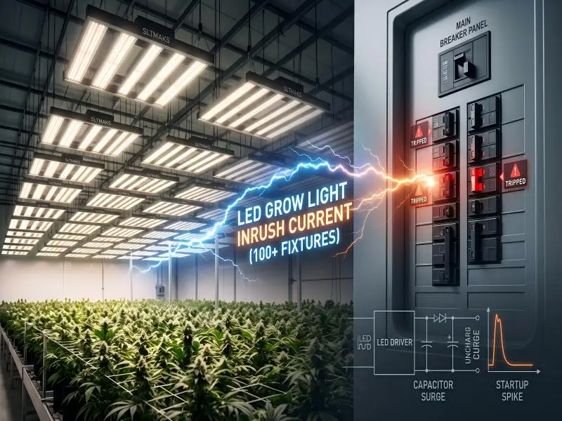
When you flip on 100+ LED grow lights across a commercial cultivation facility, the initial surge of electrical current can trip circuit breakers before steady-state operation even begins. Facility operators and master electricians often design electrical panels based solely on running wattage, only to experience unexplained morning power trips right at light onset.
This article explains the physics behind LED grow light inrush and why it creates a hidden operational bottleneck at commercial scale. You will learn what causes the startup surge inside modern LED drivers, how to calculate safe fixture counts per breaker using a dual-limit methodology, and how to design a resilient facility power infrastructure that protects both crop yield and equipment.
Table of Contents
Understanding LED Grow Light Inrush on Startup
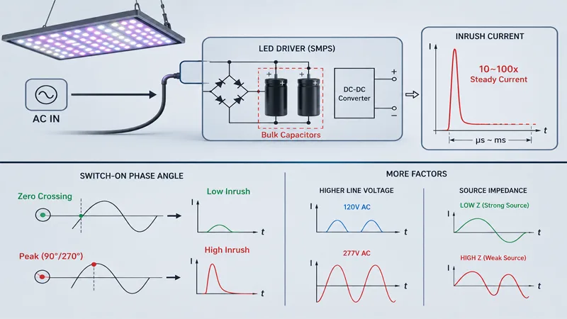
Understanding the surge requires looking inside the switch-mode power supply (SMPS) that drives high-efficiency horticultural LEDs. While LED chips themselves run on low-voltage DC power, commercial facilities supply high-voltage AC electricity.
The Role of Driver Capacitors
Every commercial LED driver contains bulk electrolytic input capacitors designed to filter, smooth, and store electrical energy. When the lighting circuit is energized, these internal capacitors are completely uncharged.
At the exact instant power is applied, uncharged capacitors present virtually zero electrical resistance. They draw a sudden spike of current to charge up—acting effectively like a momentary short circuit across the AC line. Published engineering data shows that electrical inrush current in grow lights can reach 10 to 100 times steady-state running current. Although this peak surge lasts for only a fraction of a second—typically hundreds of microseconds to a few milliseconds—its magnitude is immense.
Connecting the Surge to Your Facility
The exact magnitude of a driver’s startup surge depends on three primary facility variables: AC line voltage, source impedance, and the switch-on phase angle.
If power is switched on at the zero-crossing point of the AC sine wave, the initial voltage is low and the inrush spike is minimized. Conversely, switching on near the peak of the AC sine wave (90 degrees or 270 degrees) forces maximum voltage across the empty capacitors, generating the largest possible current surge. Higher mains voltages (such as 277V or 480V 3-phase systems) also increase overall capacitive energy transfer during energization.
When 100+ Fixtures Turn On Together
In small tent setups or craft grows with two or three fixtures, inrush current passes noticed only by a brief millisecond pulse that standard thermal breakers easily absorb. However, when scaling up to commercial indoor farms running 100, 500, or 1,000+ fixtures, simultaneous switching creates a severe cumulative current surge.
The Hidden Limiting Factor
The core challenge in commercial lighting infrastructure is that steady-state operating current suggests far more drivers can fit on a circuit than inrush limits actually allow.
Consider a practical example: A standard 20-amp, 277-volt branch circuit running 600W fixtures drawing roughly 2.16 amps each. Based strictly on continuous running current (applying the standard 80% safety cap of 16 usable amps), the circuit appears capable of handling up to 7 or 8 fixtures. However, if each driver emits a 40-amp inrush spike, 7 fixtures energizing simultaneously generate a combined 280-amp surge. This surge easily exceeds the instantaneous magnetic trip threshold of standard breakers, tripping the circuit immediately upon turn-on. In real-world installations, a circuit that permits 13 drivers by running current may only safely handle 3 or 4 drivers under simultaneous inrush conditions.
Warning: Never size commercial grow light branch circuits using running current alone. Cumulative inrush peaks can trip magnetic breaker elements even when continuous power draw remains well within safe thermal limits.
Where Nuisance Tripping Occurs
Uncontrolled inrush spikes place severe mechanical and thermal stress on multiple points throughout the facility’s power distribution tree:
- Circuit breakers: Repeated magnetic trip events cause internal calibration drift, making breakers increasingly sensitive over time.
- Contactors and relays: High current surges create electrical arcing across physical contacts during closure, leading to contact pitting, welding, or premature switch failure.
- Main transformers: Severe aggregate inrush spikes pull down transformer secondary voltage, creating instantaneous voltage sags.
These voltage sags can propagate across the facility sub-panel, triggering under-voltage faults on sensitive environmental controls, HVAC chillers, and automated fertigation pumps operating on the same electrical feeder. Over time, repeated tripping increases arc-flash hazards and degrades panel components, raising maintenance costs and fire risks.
Mitigation Strategies for Large Installations
Preventing nuisance trips across hundreds of fixtures requires intentional electrical engineering rather than oversizing breakers beyond code allowances.
Staged and Sequential Startup
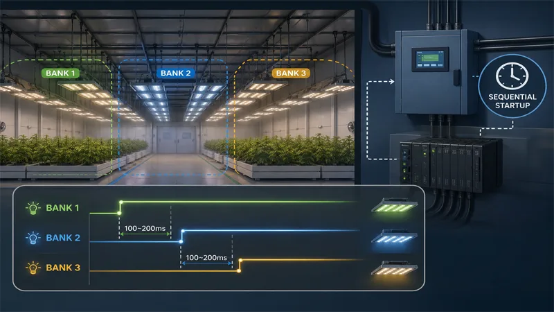
The most effective operational strategy is to eliminate simultaneous switching. By dividing grow rooms into smaller lighting banks and firing them with brief sequential delays, total peak inrush is reduced to manageable increments.
Using programmable logic controllers (PLCs), time-delay relays, or commercial smart lighting control panels, operators can stagger startup commands with 100 to 200 millisecond offsets between fixture groups. Because individual driver inrush decays in less than 5 milliseconds, a 100ms stagger gives input capacitors ample time to fully charge before the next bank energizes.
Circuit Zoning and Component Selection
Proper panel layout and heavy-duty component selection form the second line of defense:
- Phase balancing: Distribute lighting banks evenly across all three phases of a 208V, 277V, or 480V supply to prevent neutral conductor overload and severe phase imbalance during startup.
- Trip curve selection: Where local electrical codes allow, specify Type C (5–10x nominal trip threshold) or Type D (10–20x threshold) magnetic-hydraulic circuit breakers designed specifically for high-inductive and capacitive loads.
- Solid-state switching: Replace traditional mechanical contactors with zero-crossing solid-state relays (SSRs). Zero-crossing SSRs energize the circuit only when the AC voltage waveform passes through 0 volts, drastically lowering peak inrush.
Driver-Level Inrush Limiting
While panel-level controls help manage surges, addressing inrush at the fixture level is the most elegant and cost-effective solution. Advanced horticultural LED drivers incorporate internal pre-charge circuits, active negative temperature coefficient (NTC) thermistors, or switch-mode soft-start control loops.
Engineering-driven brands like SLTMAKS commercial LED grow lights build fixtures with active driver-level inrush limiting integrated directly into the power supply architecture. By restricting initial charging current inside the driver, these energy-efficient LED fixtures with built-in driver protection allow commercial cultivators to deploy hundreds of units across standard electrical panels without requiring expensive panel upgrades or complex external sequencing gear.
Calculating Maximum Drivers per Breaker
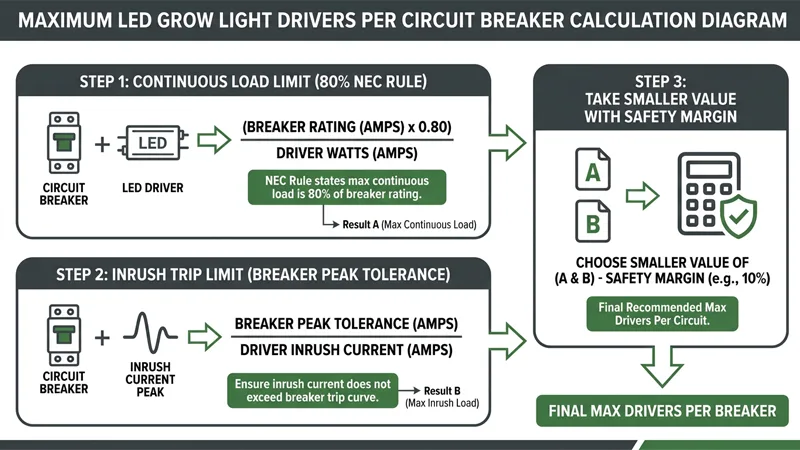
To prevent morning power trips and comply with electrical safety standards, facility managers should use a dual-limit calculation method. Safe fixture count is determined by the smaller result of two distinct calculations: continuous load capacity and instantaneous inrush capacity.
Step 1: Apply the Continuous Load Rule
Per National Electrical Code rules, commercial grow lighting that operates continuously for 3 hours or more is classified as a continuous load. Branch circuits must be sized so that continuous load does not exceed 80% of the breaker’s rated ampacity (a 125% sizing requirement for conductors and overcurrent devices).
Usable Continuous Amps = Breaker Rating (Amps) × 0.80
Continuous Limit = Usable Continuous Amps/Fixture Running Amps
For example, on a 20A breaker at 277V, usable capacity is 16A. If each fixture draws 1.8A, the continuous limit is 8.88, which rounds down to 8 fixtures.
Step 2: Check the Inrush Constraint
Next, calculate how many drivers can energize at the exact same moment without triggering the breaker’s instantaneous magnetic trip element.
Instantaneous Trip Threshold = Breaker Rating (Amps) × Trip Curve Multiplier
Inrush Limit = Instantaneous Trip Threshold/Fixture Peak Inrush Amps
If a 20A Type C breaker has a 10x magnetic multiplier (200A threshold) and each driver emits a 45A peak inrush spike, the instantaneous limit is:
200A ÷ 45A = 4.44 (rounds down to 4 fixtures)
In this scenario, while continuous load permits 8 fixtures, inrush limits restrict simultaneous switching to 4 fixtures.
Step 3: Add a Safety Margin
Field conditions rarely match laboratory testing environments. Real-world line impedance, transformer stiffness, ambient operating temperatures, and slight variations in AC phase alignment can cause field inrush to run 1.5 to 2 times higher than manufacturer datasheet averages.
Always apply a conservative safety buffer (typically 20% to 25% reduction on the calculated inrush limit) or implement 100ms sequential staging if simultaneous fixture counts approach the theoretical threshold.
NEC Compliance for Commercial Farms
Maintaining strict electrical code compliance is essential to pass local authority having jurisdiction (AHJ) inspections, ensure facility insurance coverage, and protect multi-million dollar crop yields.
Continuous Load and Conductor Sizing
Under NEC continuous load sizing standards (NEC 210.19 and 210.20), conductors and branch circuit breakers must be rated for at least 125% of the continuous lighting load.
Proper grounding, equipment bonding, and sub-panel heat dissipation must be designed and stamped by a licensed electrical engineer. Electrical inspectors look closely at continuous load calculations during commercial farm commissioning, and unmitigated inrush issues can cause inspections to fail if breaker trip settings appear undersized for the total connected load.
Budgeting for Hidden Electrical Upgrades
Factoring inrush protection into early facility engineering prevents unexpected capital expenditure during facility expansion or HPS-to-LED retrofits. Retrofitting legacy High-Pressure Sodium (HPS) rooms with high-efficiency LEDs often surprises operators: while LED running wattage is significantly lower, LED capacitive inrush is far higher than magnetic HPS ballast inrush.
According to industrial reliability studies, unexpected electrical downtime costs U.S. businesses over $150 billion annually in lost productivity, damaged equipment, and spoiled inventory. In high-density indoor cultivation, a single tripped master breaker during a lights-on cycle can disrupt photoperiod schedules, stall environmental controls, and compromise crop health.
Conclusion
Electrical inrush current in grow lights is a critical, often-overlooked engineering constraint when scaling an indoor farm past 100 fixtures. While LED technology delivers outstanding energy efficiency and PPFD uniformity, its capacitive startup profile requires deliberate electrical design.
To build a reliable commercial cultivation facility:
- Request Detailed Driver Data: Always ask your lighting supplier for peak inrush amperage (A) and pulse duration (microseconds) datasheets—not just running wattage.
- Apply the Dual-Limit Formula: Calculate both continuous load and instantaneous trip thresholds, selecting the lower fixture count for each branch circuit.
- Sequence Startup and Choose Engineered Fixtures: Implement 100–200ms sequential controller delays and choose lighting manufacturers like SLTMAKS that engineer active inrush protection directly into their driver architecture.
By engaging a licensed local electrician early and integrating driver-level inrush controls into your facility design, you protect your crop yield, maximize facility uptime, and secure long-term operational ROI.
FAQ
What is inrush current in LED grow lights?
Inrush current is the momentary spike of electrical current drawn by an LED driver when first energized. It occurs because internal bulk input capacitors are uncharged, drawing a rapid charge that can reach 10 to 100 times the fixture’s steady-state operating current for a few milliseconds.
Why do LED grow lights trip circuit breakers even if total wattage is within safe limits?
Circuit breakers feature two trip mechanisms: thermal protection for continuous overload and magnetic protection for short-time spikes. While running current may stay below the standard 80% continuous load cap, simultaneous startup of multiple fixtures generates an aggregate inrush spike that exceeds the breaker’s instantaneous magnetic trip threshold.
How do you calculate the maximum number of LED grow lights per breaker?
Use a dual-limit calculation and choose the smaller resulting fixture count:
1. Continuous Load Limit: (Breaker Amps × 0.80) ÷ Fixture Running Amps.
2. Instantaneous Inrush Limit: (Breaker Amps × Magnetic Trip Multiplier) ÷ Fixture Peak Inrush Amps.
What type of circuit breaker is best for commercial LED grow light setups?
What type of circuit breaker is best for commercial LED grow light setups?
Commercial facilities typically specify Type C (5–10x nominal trip threshold) or Type D (10–20x nominal trip threshold) magnetic-hydraulic circuit breakers, which are engineered to absorb capacitive initial power surges without nuisance tripping.
How does sequential or staged startup eliminate inrush current problems?
How does sequential or staged startup eliminate inrush current problems?
Staggered startup uses PLCs, smart lighting control panels, or time-delay relays to energize lighting banks with a 100 to 200 millisecond delay. Since driver capacitive surge decays within 5 milliseconds, staggering prevents cumulative current spikes across the feeder panel.
Do all LED grow light drivers suffer from high inrush current?
Do all LED grow light drivers suffer from high inrush current?
No. While standard drivers experience severe surges, advanced commercial fixtures incorporate active driver-level inrush protection (such as NTC thermistors, pre-charge circuits, or soft-start loops) directly within the power supply architecture to restrict initial charging current.