
An RJ14 plug clicks into an RJ14 jack. That click is the only thing the connector itself guarantees. RJ14 grow lights exist because fixture makers adopted telephone-style modular jacks for 0–10V dimming and low-voltage control signaling, and the practice spread without an industry standard behind it. No registered specification governs which contacts carry which signal, what protocol rides on them, or how many fixtures a single port may drive. Two fixtures with identical jacks can be electrically incompatible, and a controller that works perfectly in one room can fail in another with the same-looking hardware.
This guide is written for the people who have to close that gap: commercial cultivators specifying a lighting bill of materials, facility engineers integrating fixtures with a master controller, and OEM or ODM buyers commissioning custom builds. It treats the control interface as a specification problem — one resolved with written pinouts, rated limits and installation documentation — rather than a plug-and-play assumption.
The sections follow the order in which the decisions actually get made: what the connector is, how to read a pinout, how to size a daisy chain, how to protect the cabling in a working room, how to write the interface into a manufacturing brief, what an HPS-to-LED retrofit changes, and how to zone a facility so control stays legible after commissioning.
Table of Contents
RJ14 Ports on Grow Lights: What They Are & Why Compatibility Matters
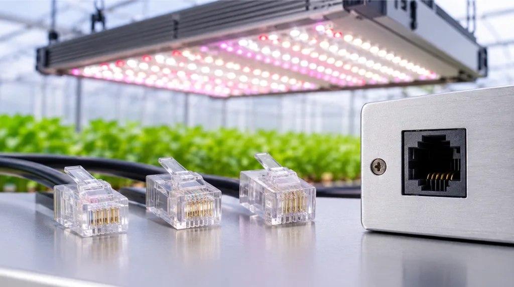
RJ14 is a registered jack designation for a six-position, four-contact modular connector — 6P4C — originally registered for two telephone lines. It shares its plastic body with RJ11 (6P2C, one line) and RJ12/RJ25 (6P6C, up to three lines). The modular connector reference is explicit that these interfaces use the same six-position body with different numbers of contacts installed, and that the connectors intermate mechanically across the variants.
That mechanical intermateability is the source of most field confusion. A 6P2C plug seats in a 6P4C jack. A 6P6C plug seats in a 6P4C jack. The latch engages, the assembly feels correct, and nothing has been verified. Whether the contacts that carry the dimming signal in the fixture line up with the contacts the controller drives is a separate question that the connector cannot answer.
In horticultural lighting, these jacks were repurposed. GrowFlux’s overview of RJ connectors for dimming notes that many legacy HPS fixtures, older LED fixtures, and even some current non-waterproof LED models use RJ-style connectors for 0–10V dimming, and states plainly that there is no official industry standard around the use of these connectors, the specific connector chosen, or compatibility across brands. The same source observes that some fixtures have since been updated to replace the RJ jack with a sealed connector — so the connector on the fixture in front of you may not match the one in the spec sheet you were sent.
Two consequences follow for anyone integrating with a master controller. First, the connector family tells you the shape of the hole, not the electrical contract. Second, because the practice is a convention rather than a standard, the contract lives in the fixture and controller documentation — and where that documentation is thin, in a written confirmation from the manufacturer. Compatibility has to be established from paper, not from the click of a plug.
How to Read and Specify a Pinout So Fixture and Controller Agree
Treat the pinout as the contract between fixture and controller. Everything downstream — adapters, splitters, cable assemblies, commissioning — depends on the two documents agreeing.
Two failure modes account for most mismatches. The first is a fixture that uses only two of the four contacts on its RJ14 jack. GrowFlux reports testing dozens of grow lights across LED, HPS, and CMH types over a decade without encountering one that needed all six wires, and recommends wiring all four positions on a four-contact connector so that a dimming connection still exists if only two positions are connected inside the light. The practical implication: a cable that carries the signal on the outer pair may work on one fixture and do nothing on another that expects the inner pair.
The second failure mode is a fixture whose pin assignment differs from what the controller expects. This is not hypothetical. Trimleaf’s adapter compatibility guide distinguishes a generic RJ adapter (LMA-14) covering most LED brands with RJ-type dimming ports from a Gavita-specific adapter (LMA-14G) required for Gavita 1000e, 1700e and other Gavita RJ fixtures. Two fixtures, same jack family, different adapters. The same guide separates adapters by protocol as well: 0–10V analog, reverse-polarity 0–10V, PWM, and relay-plus-0–10V each get their own part number.
That last point matters more than pin numbering. Before pin positions are compared, the signal type must match. Analog 0–10V dimming, PWM, and RS-485 data are different electrical languages, and a pinout that is correct for one is meaningless for another. Agrowtek’s LXD interface manual shows the range inside a single connector family: Thinkgrow fixtures use an RJ-12 data cable to a 4-pin IP65 connector; Dutch Light Innovations fixtures use standard RJ-12 phone cables and splitters; Hydrofarm/Phantom fixtures use the same RJ-12 connectors with a unique wiring configuration that requires landing conductors on terminal blocks — yellow to DC ground, green to data plus, blue to data minus. Same connector, three different electrical arrangements.
Polarity is the next check. In 0–10V sink control, the driver sources voltage and the controller sinks it; the ETC white paper on 0–10V drivers warns that control wires are polarity dependent and that crossing positive and negative when combining drivers produces flicker or a failure to dim. Reverse-polarity 0–10V exists as a distinct fixture behavior, which is why Trimleaf sells a separate adapter for it.
A workable sequence for verifying any fixture-controller pair:
- Confirm the signal protocol on both sides — 0–10V sink, 0–10V source, reverse-polarity 0–10V, PWM, or a digital bus such as RS-485.
- Confirm the voltage range and, for 0–10V, which device sources and which sinks.
- Obtain the fixture’s written pin assignment with signal names and polarity, and the controller’s matching assignment.
- Compare contact by contact, including which positions are unpopulated.
- Where the fixture uses fewer than four contacts, confirm which positions carry the signal and specify a cable that covers them.
- Record the result — the verified pairing, any adapter part number, and the date — in the project file.
Step 6 is the one that gets skipped and the one that pays for itself at the next service call. The pinout also belongs in the manufacturing brief, covered later, where it gets fixed before tooling rather than discovered at commissioning.
What Determines How Many Fixtures Can Share a Daisy Chain
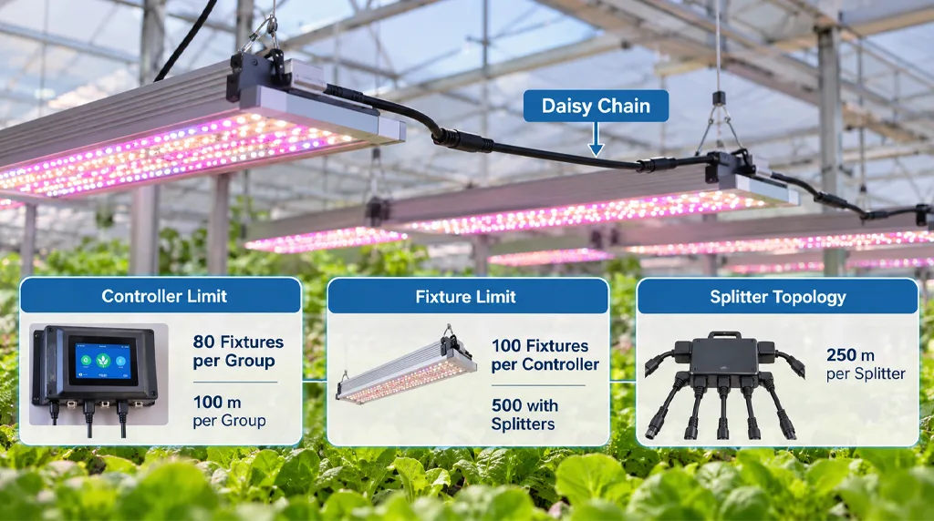
Chain size is governed by three separate limits, and they come from different documents. Conflating them is how rooms end up with a controller output driving more fixtures than it is rated for, or a cable run that exceeds the length the manufacturer validated.
Published chain limits from two different products under two different topologies. The Active Grow figures are per group on a two-group controller; the Gavita figures are per controller or per daisy chain and depend on whether splitters are used. Neither set transfers to a third product, and the binding limit for any bill of materials is the lower of the controller and fixture figures for the exact models installed.
Controller output rating. The controller’s own documentation states how many fixtures one output or group can drive. The Active Grow Plant Lighting Smart Controller, as listed by Rightbud, manages up to 160 fixtures across two groups at 80 fixtures per group, and specifies a maximum cable length per group of 328 ft (100 m). Those are the controller manufacturer’s published figures for that model.
Fixture-side chain limits. The fixture manual states its own limits, which may be more permissive or more restrictive. The Gavita Pro 900e LED instructions permit a maximum of 100 LED fixtures on one controller in a simple daisy chain, up to 500 fixtures per daisy chain when splitters are used, and up to 1,000 fixtures across two channels in a splitter-based topology. The same manual states a maximum cable length per splitter of 250 m (100 interconnect cables). The Gavita HPS commercial instructions use the same 100-fixture daisy-chain and 500-fixture splitter figures for the DE fixtures.
Splitter-based expansion. Where splitters are permitted, the fixture manual defines the topology and the length budget per splitter. Splitters are not a generic multiplier; they are a documented topology with its own limits.
Set the two published examples side by side and the point becomes concrete. One controller is rated for 80 fixtures per group with a 100 m cable limit per group. One fixture family permits 100 fixtures per controller in a simple chain and 500 with splitters, with a 250 m limit per splitter. Neither number is wrong. They describe different products under different conditions, and neither transfers to a third product.
The only defensible chain size for a given bill of materials is the lower of the two written limits — controller and fixture — for the exact models being installed, adjusted for the topology actually built. A few practical rules follow:
- Get both limits in writing, for the exact model numbers, before the layout is frozen.
- Apply the cable-length limit per group or per splitter as the manufacturer defines it, not as a total across the room.
- If splitters are used, confirm the fixture manual permits them and follow its topology diagram rather than improvising.
- Record the resulting fixture count per output on the as-built drawing so the next person to add fixtures knows the headroom.
Where the two documents conflict or one is silent, the question goes to both manufacturers before installation, not after.
How to Keep RJ14 Control Cabling Durable and Inspection-Ready in Humid, High-Dust Rooms
The modular jack is the weak point of an otherwise industrial installation. GrowFlux’s assessment is direct: RJ-style connectors are convenient and economical, but they are not waterproof and may not offer the best reliability in a commercial setting. That is the design constraint to work around, not a defect to argue with.
Start with what an IP rating actually covers. The IP code is defined in IEC 60529 and consists of two mandatory digits: the first for protection against solid objects and contact, the second for water ingress. An X in either position means no test value was specified for that criterion. Two scope rules matter in a grow room.
First, water ratings are not cumulative above IPX6 — a device rated IPX7 for immersion is not necessarily rated for the water jets of IPX5 or IPX6, and a device that passes both is marked with both, for example IPX5/IPX7. Second, the rating applies to the enclosure as tested. An enclosure rating does not transfer to an unmated connector, and it does not survive a plug left hanging out of its jack.
That second point is where most grow-room control failures originate. The fixture housing may be well sealed; the RJ14 jack on its face is an open cavity with exposed contacts, sitting in a room that runs at high humidity and cycles through irrigation events and condensation.
The design response is routing and protection rather than a higher number on a datasheet:
- Route control cable away from irrigation lines, spray zones, and surfaces where condensation collects and drips. Overhead runs that sag are collection points.
- Protect terminations. Where the fixture manual or an accessory kit provides a dummy plug or cap for an unused port, keep it fitted — Gavita’s manual notes the dummy is required for standalone operation and should be kept safe when removed.
- Separate control conductors from line-voltage conductors. Under NEC Article 725, Class 2 and Class 3 circuits must not be placed in the same enclosure, raceway or cable as electric light, power and Class 1 conductors except under the specific permissions in 725.136(B) through (J); where they share an enclosure solely to connect to the same equipment, a minimum ¼-inch separation is required. The EC&M summary of Article 725 sets out those rules. Where control and line-voltage wiring share a conduit, the ETC white paper notes that the control conductors’ insulation must be rated for line voltage.
- Fit the ferrites. Gavita’s repeater bus kit includes EMC ferrite snap-on cores, and the manual instructs mounting them on both cable ends close to the RJ connectors. The 900e LED manual also warns against coiled cords and instructs keeping mains leads separated to prevent electromagnetic interference. These are EMC measures specified by the fixture manufacturer, not optional accessories.
- Respect the cable-length limits for EMC as well as for signal integrity. The same manuals that set fixture counts also set length budgets.
Documentation is the other half of inspection readiness. An inspector tracing a control circuit needs to see where it is classified, how it is separated from line voltage, and what it connects to. Label both ends of every control run, keep the as-built drawing current, and retain the fixture and controller manuals with the electrical drawings. A circuit that cannot be traced is a finding waiting to happen.
How to Write an ODM/OEM Brief That Pins Down the Control Interface Before Tooling
For a buyer commissioning custom fixtures, the control interface is cheapest to specify and most expensive to change. A jack position, a contact count, or a pin assignment fixed after the enclosure tooling is cut becomes a re-tooling project. The brief should close every interface question before the first enclosure drawing is released.
Arithmetic illustration only, using the control-current range stated in the ETC white paper (10 µA to 2 mA per driver, typically 0.5 mA) against a controller able to sink 100 mA. It shows how widely a sink-current budget can vary with per-driver current; it is not a fixture-count recommendation, and the actual figure depends on the drivers and controller in the bill of materials.
The following items belong in the ODM/OEM brief as written requirements, each with a named responsible party and an acceptance criterion:
Connector definition. Connector type, position, and contact count (for example, 6P4C), location on the enclosure, orientation, and whether the port is an input, an output, or both. State whether a sealed connector is preferred over an open modular jack, and if a modular jack is retained, specify the cap or dummy requirement for unused ports.
Pin assignment. A contact-by-contact table with signal names, polarity, and which positions are populated. This is the single most important page in the brief. It should be signed off by both the fixture design team and the controller manufacturer or the integrator who owns the controller.
Signal protocol and voltage range. 0–10V sink or source, reverse-polarity 0–10V, PWM, or a digital bus such as RS-485. State the voltage range, the source-and-sink relationship, and the behavior at the extremes — what the fixture does with the control line open and with it shorted. The ETC white paper notes that 0–10V drivers typically output maximum with control lines open and minimum with them shorted, so the failure mode is defined by the driver design and should be confirmed, not assumed.
Chain limits. Maximum fixtures per controller output, maximum fixtures per chain, and maximum cable length per group and per splitter. These must be stated as fixture-side limits that will be validated against the named controller’s published limits.
Connector environmental specification. Ingress protection of the mated connector, not just the housing; mating durability in cycles; retention force; and the installation method that preserves the rating.
Labeling and documentation deliverables. Port labels on the fixture, a pinout drawing, an installation manual section covering controller connection, and a declaration of the limits above. These are deliverables, not favors.
Compatibility test protocol. A defined test against the named master controller: connect the specified number of fixtures at the specified cable length, drive the full dimming range, verify the minimum and maximum output levels, verify behavior on loss of control signal, and record the results. The protocol should name the controller model and firmware version.
Two habits make the brief stick. First, tie each item to a document the supplier must return — a drawing, a test report, a manual page — rather than to a verbal assurance. Second, hold a pre-tooling review where the pinout table and the compatibility test protocol are walked through against the controller documentation. The cost of that review is a meeting; the cost of skipping it is a tooling change and a room full of fixtures that do not dim.
How an HPS-to-LED Retrofit with Centralized Control Changes the Wiring and Inspection Conversation
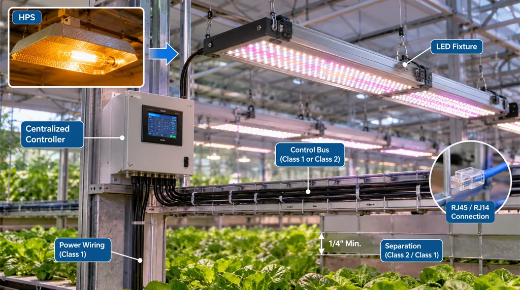
An HPS-to-LED retrofit with centralized control changes the electrical architecture, not just the lamp. Legacy HPS fixtures were typically controlled at the ballast, often per fixture or per small group. A centralized low-voltage control bus concentrates dimming and scheduling in one controller and distributes a signal across the room. That shift creates a new network that has to be classified, separated, and documented.
Classification. The control wiring is a low-voltage network, and its Class 2 or Class 1 status is determined by the device that sources the signal. The ETC white paper is clear that the LED driver is the device sourcing the voltage, so the driver’s construction determines whether the signal wiring is Class 1 or Class 2, and that the manufacturer and datasheets should be consulted.
The same paper notes that reclassifying a circuit from Class 2 to Class 1 requires eliminating every Class 2 marking on all devices on the circuit and running the circuit with Class 1 wiring methods along its entire length. For a retrofit, that means the classification decision is made fixture by fixture and recorded, not assumed from the old installation.
Separation. Once classified, the separation rules apply. Class 2 and Class 3 conductors cannot share enclosures, raceways, or cables with electric light, power, and Class 1 conductors except as permitted in Article 725, and where they share an enclosure solely to reach the same equipment, a ¼-inch separation is required. In a retrofit, existing conduit and cable trays are often already full, and the temptation to pull control cable through the power raceway is real. The code answer is no, absent the specific permissions.
Mixed fixture populations. Legacy HPS fixtures with RJ-style ports may use different pinouts than the new LED fixtures going in beside them. Gavita’s HPS commercial instructions and the 900e LED instructions both describe RJ-based control, but they are different products with their own manuals and their own connection hardware — the LED manual, for instance, lists RJ45 and RJ14 terminal connectors in its adapter kit. In a room where old and new fixtures share a controller, each model needs its own verification against the controller, and the as-built drawing needs to show which model sits on which output.
Documentation burden. The retrofit produces a new set of documents: the control classification per circuit, the separation method, the per-model pinout verification, the chain limits per output, and the commissioning test results. These are what an inspector will ask for and what the next technician will need. Energy and rebate economics may motivate the project, but they do not reduce the documentation the installation requires.
A retrofit checklist:
- Classify each control circuit as Class 1 or Class 2 based on the sourcing device, and record the basis.
- Verify separation from line voltage for every run, including reused raceways.
- Verify the pinout of every fixture model on the bus, old and new, against the controller.
- Confirm chain limits per output using the lower of the fixture and controller figures.
- Commission with a recorded dimming-range test and retain the results.
How to Zone a Facility for Independent Dimming, Schedules and Alarms
Zoning is where the control design meets the cultivation plan. A zone is the smallest area that can be dimmed, scheduled, and alarmed independently. Get the zones right, and the controller configuration follows; get them wrong and every schedule change becomes a compromise across the room.
Group fixtures by what needs to behave differently. Useful boundaries include crop or cultivar, tier in a vertical rack, propagation versus vegetative versus flowering areas, and environmental sub-zones with different temperature or humidity setpoints. Two benches under the same photoperiod and the same target intensity can share a zone; a propagation shelf and a flowering canopy cannot.
Then align zone boundaries with the controller’s physical outputs. Each zone should map to a defined controller output or group, and the fixture count on that output must sit within the lower of the controller’s and fixture’s published limits. Cable-length limits apply per group or per splitter as the manufacturer defines them, so a zone that spans a long room may need to be split even if the fixture count is fine. The controller example cited earlier — 80 fixtures per group with a 100 m maximum cable length per group — shows how a count limit and a length limit can bind independently.
Alarm routing deserves the same planning as dimming. Decide per zone how a loss of control signal is annunciated, where an over-temperature condition reports, and who is notified. The point is locatability: when an alarm fires at 02:00, the responder should be able to identify the zone and the affected output from the alarm text alone. A controller that reports “fault” without a zone identifier has told the operator nothing useful.
Zoning decisions also constrain the pinout and chain work described earlier. A zone boundary that splits a daisy chain forces a decision about which controller port feeds which room, and that decision belongs on the as-built drawing alongside the pinout verification and the chain limits. Record, per zone: the controller output, the fixture model and count, the cable length, the protocol and adapter used, and the alarm routing. That table is the operating document for the room.
Further Reading and Verification Checklist
The authoritative sources for any specific installation are the fixture manual and the controller manual for the exact models in the bill of materials. The figures cited in this guide — 80 fixtures per group with a 100 m limit, 100 fixtures in a simple daisy chain and 500 with splitters, 250 m per splitter — are examples of published limits from specific products. They illustrate the range of what manufacturers publish; they are not universal specifications and should not be applied to a different model without confirmation.
Procurement checklist:
- Written pinout from the fixture manufacturer, with signal names and polarity, for the exact model.
- Written pinout or input specification from the controller manufacturer for the exact model and firmware.
- Confirmed signal protocol and voltage range on both sides, including source/sink relationship for 0–10V.
- Written chain limits from both manufacturers: fixtures per output, fixtures per chain, cable length per group and per splitter.
- Confirmed splitter topology and permission, if splitters are used.
- Connector ingress protection stated for the mated connector, plus the installation method that preserves it.
- Adapter part numbers identified where pinouts or protocols differ.
- Compatibility test protocol agreed, naming the controller model and firmware version.
- Labeling and documentation deliverables listed in the purchase agreement.
- As-built drawing showing zones, controller outputs, fixture models, cable lengths, and alarm routing.
- Commissioning test results recorded and retained with the electrical drawings.
Reference documents worth keeping with the project file: the Gavita Pro 900e LED instructions and the Gavita HPS commercial instructions for fixture-side chain limits and EMC measures; the Active Grow controller listing for a controller-side example; the ETC white paper on 0–10V drivers for protocol, polarity and Class 1/Class 2 guidance; the EC&M Article 725 summary for separation rules; the IP code reference for rating scope; and GrowFlux’s RJ connector overview for the state of the connector convention.
FAQ
Does an RJ11 plug fit an RJ14 jack?
Mechanically, yes. Both use the six-position modular body, and the connectors intermate across the variants. Electrically, not necessarily — the RJ11 plug carries two contacts where the RJ14 jack has four, so whether the signal lands on the right contacts depends on the fixture’s pin assignment, which the connector cannot tell you when working with various RJ14 grow lights.
Are all six positions used?
RJ14 has four contacts in six positions. Many grow lights use fewer than four — GrowFlux reports not encountering a fixture that needed all six wires across dozens of tested lights, and recommends wiring all four positions where the design allows so a two-contact fixture still connects. Confirm the populated positions from the fixture’s written pinout when setting up RJ14 grow lights.
Will any RJ14 fixture work with any master controller?
No. The pinout and the signal protocol must both match. A generic RJ adapter covers many LED brands, but Gavita RJ fixtures need a Gavita-specific adapter, and PWM fixtures need a different adapter again. Physical fit establishes nothing, especially for specialized RJ14 grow lights.
What single document should I request first?
The fixture’s written pinout, with signal names and polarity, together with the controller’s rated limits for the exact model. Those two documents answer the compatibility and chain-size questions that everything else depends on when purchasing or installing RJ14 grow lights.