Introduction
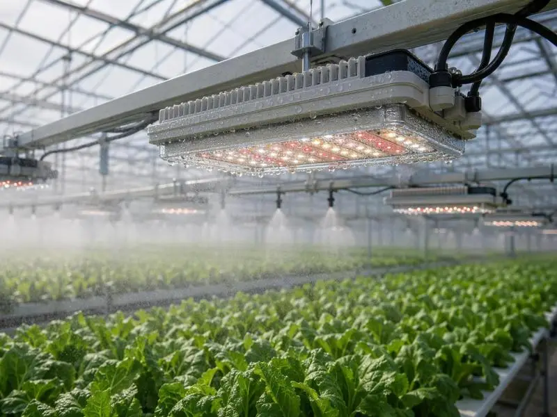
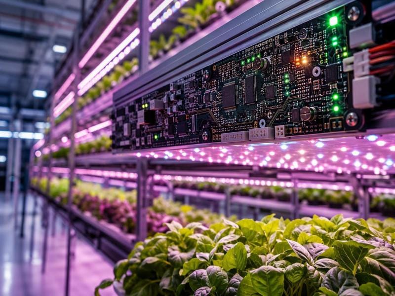
A vertical rack compresses the distance between the light source and the canopy to a few tens of centimeters. At that throw, the printed circuit board stops being a passive carrier for LEDs and becomes the component that sets canopy uniformity, junction temperature, and service life. “Custom PCB grow lights” in this context means a board engineered against a specific rack geometry, a stated power density, and a defined compliance envelope — not a catalog panel with a different label on the enclosure.
This guide follows the sequence a board specification actually moves through: substrate and stack-up, the thermal path from die to rack frame, current-carrying and clearance rules, optical placement at short throw, the documentation set that should gate approval, and replacement planning. It draws on published design-practice and fabrication guidance, UL 8800 and DesignLights Consortium (DLC) program material, and IES LM-80/TM-21 methodology. Nothing here reports first-hand testing; where a figure comes from a source, the source’s own conditions travel with it.
Table of Contents
What Makes a Vertical-Farm Board Different from a General Grow Light Board
A general-purpose grow light board is designed against a mounting height measured in meters. A vertical-farm board is designed around one measured in centimeters, and four conditions change with it.
Near-field optics. Published vertical-farm module design material describes tier clearances of roughly 0.40–0.75 m between the growing surface and the underside of the tier above, with the LED surface sitting 0.15–0.40 m above the canopy depending on crop stage and mounting position (Lumistrips). At 0.2–0.4 m, PPFD distribution at canopy level is governed by the near-field behavior of the LED package and any secondary optic, not by the far-field pattern that dominates a greenhouse fixture at 3–8 m. Hot spots and edge gradients that average out over a long throw become visible and agronomically significant.
Radiant heat toward the canopy. Close mounting removes the thermal buffer that mounting height provides in a greenhouse. The module must be managed to limit radiant heat emission toward the plants below, not only to protect its own LEDs.
Multi-tier service. A board mounted inside a 0.40–0.75 m tier cannot be reached from above. Connector position, harness routing, and mounting-hole pattern determine whether a module can be swapped in place or whether the tier has to come apart.
Elevated ambient temperature and humidity. The mounting surface in a warm tier runs above ordinary room temperature, and irrigation and transpiration keep humidity high. Both conditions are explicit evaluation points in UL 8800, discussed below.
The performance quantity that layout actually influences is PPFD at canopy level, not PPF. PPF, in µmol s⁻¹, measures the total photons a luminaire emits per second regardless of destination; it says nothing about what any plant receives. A specification that quotes PPF without PPFD at defined mounting heights and spacings is incomplete for installation planning (Lumistrips).
What a board-level customization can change: substrate and dielectric, copper distribution, LED pitch and placement, trace widths, connector locations, mounting pattern, and the thermal resistance of the stack itself. What it cannot change: rack frame stiffness, airflow and plenum design, driver topology, enclosure ingress rating, or the facility’s ambient control. Those belong to the luminaire and facility scope, and the supply agreement should say who owns each.
Reading a Supplier’s Design as Engineered or Relabeled
The useful question is not whether a supplier offers “custom” boards but whether a design was performed against your rack. Four pieces of evidence separate the two cases.
A junction-temperature calculation tied to your inputs. Ask for the calculation at your drive current and your measured ambient at the mounting surface, with the assumed thermal resistance of each layer stated. A number without its assumptions is not a thermal design; it is a number.
A stack-up drawing with dielectric thickness. The dielectric is the thermally and electrically critical layer in a metal-core board. Published MCPCB construction data puts it at 50–200 µm, with thinner dielectric improving heat transfer and thicker dielectric improving voltage isolation (AtlasPCB). A drawing that omits the thickness has omitted the trade-off.
A substrate choice justified by power density. The justification should reference your watts per unit area and your ambient, not a generic claim that metal-core is better.
A mechanical outline matched to your mounting pitch. Hole positions, board outline, and connector orientation should correspond to the rack drawing you supplied, within a stated tolerance.
One limit is worth stating plainly. LM-80 data describes an LED package, array, or module tested under controlled case temperatures with an external current source; during lumen-maintenance testing the LED is allowed to cool to room temperature and is measured at 25 °C air (DOE/SSL presentation on LM-80-08 scope). A datasheet quoting only component-level LM-80 results therefore says nothing about the assembled luminaire in your tier. Likewise, a supplier who cannot state the assumptions behind a thermal figure has not shown that the design was done — only that a figure exists.
Substrate and Stack-Up Selection by Power Density
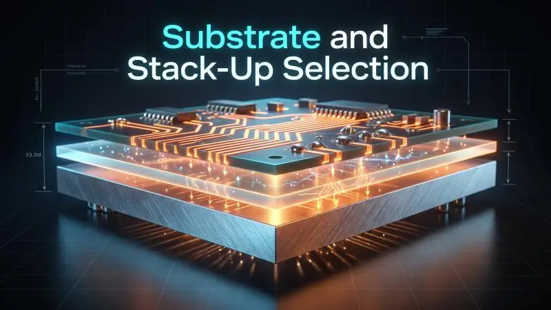
Substrate selection is a conditional decision. The published thermal-conductivity figures below are mostly dielectric-layer values for metal-core constructions, not the conductivity of the base metal, and they should be read that way.
| Material | Reported thermal conductivity | Reported cost index | Typical reported use |
|---|---|---|---|
| FR-4 (standard) | 0.25–0.3 W/m·K | 1x | Low-power indicators |
| Aluminum MCPCB | 1.0–4.0 W/m·K (dielectric) | 3–5x | General lighting, street lights |
| High-Tg MCPCB | 6.0–8.0 W/m·K | 6–8x | Automotive, industrial |
| Copper MCPCB | 3.0–6.0 W/m·K | 8–10x | High-power spotlights |
| Ceramic DBC | 20–30 W/m·K (Al₂O₃); 170–230 W/m·K (Cu) | 15–25x | Laser diodes, aerospace |
Calculated from Rθ = t/(k·A) as presented in a fabricator technical guide; these are calculated examples for the dielectric layer only, not measured fixture data, and not total junction-to-ambient resistance. Only the 75 µm/3 W·m⁻¹·K⁻¹, 100 µm/1 W·m⁻¹·K⁻¹, and 150 µm/3 and 4 W·m⁻¹·K⁻¹ points are source-stated; the remaining points follow the same formula.
Source: PCBElec thermal-management guide. A separate fabrication source gives standard FR-4 at 0.3–0.4 W/m·K and MCPCB dielectrics at 1.0–8.0 W/m·K (Andwin PCB). The ranges overlap across sources; treat them as order-of-magnitude guidance for comparing families, not as specifications for a particular laminate.
Conditions that shift the answer.
- Power per LED. One substrate guide puts aluminum MCPCB as the correct specification above roughly 3 W per LED, in ambient above 30 °C at the module mounting surface, at high LED density with limited spacing, and where an L80 or L90 lifetime at 50,000+ hours is a procurement requirement (Lumistrips).
- Power density. A selection comparison places FR-4 as preferred below 1 W/cm² and aluminum MCPCB as required above 2 W/cm², with the middle band a judgment call (AtlasPCB).
- Layer count. The same comparison treats four or more layers as an FR-4 condition and one to two layers as the MCPCB norm. A board carrying a microcontroller with 48+ I/O pins likely needs multilayer FR-4 regardless of thermal preference.
- Voltage isolation. Aluminum MCPCB is listed as suitable below 500 V, the dielectric limit in that comparison; published MCPCB breakdown voltage is 3–6 kV.
- Whether the board is the heatsink. If there is no external heatsink, the board must carry the spreading function itself.
Double-sided MCPCB. Two-layer MCPCB with circuitry on both sides of the metal base exists, but it requires thermal vias through an aluminum core that must be electrically isolated, and the reported cost is 4–6x single-sided MCPCB. At that price, the same source argues a conventional multilayer FR-4 with copper coins or heavy copper thermal planes often provides better value. Standard single-sided MCPCB design rules — minimum trace/space of 4/4 mil, with 6/6 mil more common in production — suit power and LED circuits where trace count is low.
Flatness. A rigid aluminum base does not conform to a mounting surface the way FR-4 does. For boards bolted directly to a chassis, specify bow and twist of 0.5% or tighter. Copper balancing — equal copper weight on both sides — is the standard countermeasure against warpage in aluminum LED boards.
Designing the Thermal Path from Junction to Rack
Heat leaves an LED through a series of resistances: die to solder joint, solder to copper, copper through the dielectric, dielectric into the base metal, base metal through the interface material, interface into the rack frame or heatsink, and finally convection to the tier air. Each interface adds to the total, and the total sets the junction temperature.
In an aluminum MCPCB, the path is short: heat crosses 35–70 µm of copper, then 75–200 µm of filled dielectric rated 1.0–3.0 W/m·K, then enters the aluminum base plate at roughly 200 W/m·K. Reported pad-to-base thermal resistance is typically 5–15 °C/W per square centimeter, described as a 5–10x improvement over FR-4 (AtlasPCB).
Where layout changes the outcome.
- Copper distribution. Copper that is clustered around the LEDs and absent elsewhere creates lateral temperature gradients across the board. Balanced copper spreads heat and limits warpage at the same time.
- Dielectric thickness. This is the central trade-off in a metal-core stack: thinner dielectric lowers thermal resistance and raises capacitance and leakage risk; thicker dielectric raises isolation and thermal resistance. The 50–200 µm range is where the decision is made.
- Thermal vias. Where a multilayer FR-4 approach is chosen instead, thermal via arrays under the LED pads carry heat to internal copper planes. The fabrication guidance is to avoid vias directly in the LED thermal pad area on MCPCB, where they cause solder voids; the via-array strategy belongs to the FR-4 alternative.
- Interface material. The board-to-heatsink interface is a real resistance, not a formality. Surface finish matters: ENIG is preferred for LED thermal pads because it is flat and solderable, while HASL’s uneven topology raises interface resistance.
- Assembly contact. MCPCB mating surfaces are prepared by polishing or anodize removal before assembly; a contaminated or oxidized interface erodes the calculated margin.
What the penalty looks like. One fabrication source states that overheating reduces luminous efficacy by 10–20% per 10 °C rise above 25 °C (PCBElec). That figure is stated for a 25 °C reference, which is not the ambient inside a warm tier; use it to understand the direction and rough magnitude of the penalty, not as a prediction for your rack. A second source reports that for every 10 °C above the rated maximum junction temperature, LED lifespan typically falls by 30–50% (Andwin PCB) — a different quantity, referenced to the rated maximum rather than 25 °C, and not interchangeable with the efficacy figure.
Where PCB layout ends. The board can lower resistance through its own stack, its copper, and its interface. It cannot fix a rack frame that does not conduct, an airflow pattern that stalls in a tier, or a plenum that recirculates hot air. Those belong to luminaire and facility design. The supplier scope should name which party owns the frame, the interface specification, the airflow assumption behind the junction-temperature calculation, and the ambient temperature the calculation was run at.
Current-Carrying Rules, Clearance and Creepage
Trace width. Published guidance for LED strings operating at 350 mA to 1000 mA calls for a minimum 0.3 mm trace width for power distribution, increasing to 0.5–0.8 mm for current paths exceeding 2 A, sized per IPC-2152 current-carrying practice (Andwin PCB). The metal base spreads heat, but that benefit does not excuse undersized traces: a trace that is thermally assisted and still undersized produces a localized hot spot at the narrow point, which is exactly where the dielectric is stressed.
Generic functional spacing for PCB layout, keyed to maximum DC or AC peak voltage between conductors, for external uncoated conductors at elevations up to 3,050 m. It is not the final safety spacing for a certified horticultural luminaire; that depends on insulation type, pollution degree, altitude, and the product safety standard. Above 500 V, the standard switches from a table to a per-volt calculation (0.005 mm/V in this column), so no single bar is shown for that band.
Clearance. IPC-2221 sets minimum conductor spacing as a function of the voltage between conductors and the coating condition. Representative values from the standard’s table, as reproduced by ProtoExpress:
| Voltage between conductors | Internal conductors | External, uncoated, up to 3050 m | External, permanent polymer coating |
|---|---|---|---|
| 0–15 V | 0.05 mm | 0.1 mm | 0.05 mm |
| 31–50 V | 0.1 mm | 0.6 mm | 0.13 mm |
| 101–150 V | 0.2 mm | 0.6 mm | 0.4 mm |
| 301–500 V | 0.25 mm | 2.5 mm | 0.8 mm |
| >500 V | 0.025 mm/V | 0.005 mm/V | 0.00305 mm/V |
Above 500 V, the standard switches from a table to a per-volt calculation, and the per-volt coefficients differ by conductor location and coating. A board carrying only the low-voltage LED string sits in the first rows; a board that also carries mains-adjacent driver circuitry does not. Confirm which condition applies to each net rather than applying one row to the whole board.
Driver-side layout. Where the board carries control electronics as well as LEDs, keep switching nodes and their return currents away from the LED power distribution. Texas Instruments’ EMI layout guidance is built around the principle that every signal has a return path and that the loop area between them is what radiates; it recommends a ground plane under signal traces where a four-layer board is used, gridded ground where only two layers are available, and isolation of digital power and ground from analog and high-power nets (TI SZZA009).
That document targets two-layer boards in automotive and consumer environments at a noise level more stringent than FCC Part 15 — a stricter case than a grow light needs, which makes its zoning advice a safe default rather than a minimum.
The practical consequence for a dense horticultural board: if it needs a microcontroller, dimming interface, and sensor front end alongside the LED strings, the layer count required for routing and return paths may force a multilayer FR-4 design regardless of what the thermal analysis prefers. In that case, the common architecture is a hybrid — an FR-4 control section connected to an MCPCB LED section — rather than a compromised single board.
Optical Layout: Pitch, Density and Uniformity at Short Throw
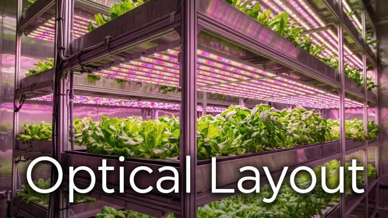
Standard dome-lens LEDs emit with a half-intensity viewing angle of roughly 60–70°, close to a Lambertian distribution. At 10–30 cm canopy-to-fixture distance, that broad cone produces heavy overlap between adjacent LEDs and steep gradients toward the tray edge (Lumistrips optics guide).
At short throw, the primary design variables are module pitch and LED density. Secondary optics contribute relatively little loss at these distances because beam-shaping requirements are modest; the same source notes that narrow-to-medium beam angles of 40–80° combined with careful strip spacing optimize uniformity in vertical tiers. End effects — lower PPFD at strip ends than at the center — become significant at very short mounting distances and are mitigated through optic selection and strip overlap design.
The nonlinearity that catches boards designed for a fixed height. A crop that grows 5 cm upward at a 20 cm mounting distance moves to 15 cm, and PPFD rises by (20/15)² = 1.78, a 78% increase, with no change to the driver setting (Lumistrips vertical-farm module design). A board whose LED spacing was optimized for one canopy height will be over-lit at the end of the cycle and under-lit at transplant unless the rack allows the module to be raised as the crop grows — or unless the spacing was chosen for the worst case in the cycle.
There is a second limit on the inverse-square relationship. Closer than roughly five times the largest source dimension, the source cannot be treated as a point, and the inverse-square law underestimates PPFD falloff. That is the near-field regime that governs vertical-farm close-canopy optics, and it is why a uniformity simulation run with a point-source model will not match the tray.
Verification at canopy level. A designed spectral ratio is a claim about the fixture, not about the plant. Confirming it requires a spectrally corrected quantum sensor — standard silicon photodiodes misread narrow-band LED spectra because of wavelength-dependent response — measured at multiple grid points across the growing area, with results used to calculate the min/avg uniformity ratio. Modern spectral sensors can measure total PPFD and spectral composition simultaneously, which allows a grower to confirm that a specified red/blue ratio is actually arriving at the canopy after selective absorption by glazing and reflection from growing surfaces. Uniformity should be characterized as PPFD or irradiance ratios across defined tray geometries, not as a lux-based index.
Documentation and Test Evidence to Require Before Approval
Each document in a lighting submittal covers a different thing. The most common procurement error is treating one as evidence of another.
LM-79 measures a complete solid-state lighting product — optical and electrical performance — in an accredited laboratory. It does not by itself predict useful life or prove safety certification. Request the full report for the exact tested model and configuration, with input conditions and the measurement method, not a cropped summary.
LM-80 plus TM-21 addresses lumen maintenance of the LED package, array or module. LM-80 specifies operation at three case temperatures (55 °C, 85 °C, and one selected by the manufacturer), case temperature held within ±2 °C, relative humidity below 65%, a minimum of 6,000 hours with data collected every 1,000 hours, and constant current at rated voltage (DOE/SSL). TM-21 provides the projection method. The same presentation records a manufacturer recommendation to extrapolate no more than 6x the test time, and notes that TM-21 is referenced in ENERGY STAR guides and DLC qualification criteria. A projection beyond that multiple is outside the method’s stated practice.
In-situ temperature measurement (ISTMT) is what connects the two. The DLC’s own technical material states the purpose directly: the ISTMT relates the LM-80 test conditions to how the LED is actually used, so the temperature measurement point must be consistent from LM-80 to ISTMT (DLC webinar slides). The TM-21 calculation takes LM-80 parameters, LM-80 lumen-maintenance data in order of increasing temperature, and the ISTMT drive current and highest measured temperature. Without the in-situ data, the projection describes a laboratory condition, not your tier.
The listing and qualification records. For a US installation, request the NRTL directory record with the file or control number, the exact model suffix, voltage, mounting configuration, and wet rating. Where a utility program applies, verify the exact model on the current DLC Horticultural Qualified Products List (QPL) and check its status — the QPL runs on a published revision cycle, with Hort V4.0 active from April 18, 2025 and Hort V3.0 scheduled for delisting on January 6, 2026 (DLC horticultural lighting page).
Two cautions. A QPL listing is a performance qualification, not a safety listing, and it does not guarantee a rebate in every location. And neither a listing nor a qualification proves yield: the UL horticultural material is explicit that the optimal spectrum and intensity for one species may not be optimal for another (UL Solutions infosheet).
Safety and Compliance Evidence for a US Installation
UL 8800, introduced in 2017, is the published safety standard for lighting equipment and grow systems intended for horticultural use and installed in accordance with the National Electrical Code. Its scope covers luminaires and, where a horticultural system is employed, can also include lampholders, wire harnesses, plugs and connectors, LED packages, drivers, lamps, and hardware and structures (UL 8800 brief).
What it adds over a general luminaire standard.
- Elevated ambient testing. Temperature testing is conducted at the product’s anticipated ambient rating rather than the 25 °C used for a typical LED luminaire (In Compliance). This is the provision that matters most in a warm upper tier.
- Damp location suitability, evaluated per ANSI/UL 1598/CSA C22.2 No. 250.0 for fixed luminaires.
- Ingress protection (IP) testing, classifying protection against solid objects and water.
- Photobiological safety assessment, addressing eye and skin exposure to the light sources used in horticultural systems. The underlying evaluation framework is IEC/EN 62471, which defines exposure limits and classification (Intertek).
- UV exposure of polymeric materials, which can become brittle under UV from the sun in a greenhouse or from the luminaire itself.
- Wiring and connection methods that support the frequent raising, lowering, and repositioning that horticultural systems require.
The standard also assigns responsibility at the facility level: it is the plant growth facility’s job to address the risks identified in the standard and to ensure that people entering growing areas while lights are on are aware of them and that safeguards are in place (UL 8800 scope, clause 1.5).
What the marks do not mean. An NRTL mark — UL Listed or ETL Listed, commonly evaluated to UL 8800 for horticultural equipment — is a third-party safety evaluation with ongoing follow-up. It does not prove light output, crop yield, or rebate eligibility. CE marking is the manufacturer’s declaration of conformity with applicable EU legislation and is not automatically a third-party certificate. RoHS restricts specified hazardous substances and is not established by a logo alone. FCC Part 15 addresses radio-frequency emissions for applicable digital or unintentional-radiator functions and is not an electrical-safety certification; many non-wireless products carry no FCC ID. ISO 9001 certifies a quality-management system for an organization and scope, not an individual product’s safety or durability (grow-lights.net certification guide).
One dependency is worth noting for planning: certification to UL 8800 is a stated prerequisite for a product to be added to, or remain on, the DLC horticultural QPL (UL Solutions). A utility rebate path therefore runs through the safety listing, not around it.
Finally, the Authority Having Jurisdiction (AHJ) inspects the installation. The listing supports that inspection; it does not replace it. Local code review, the wet/damp designation for the actual mounting location, and the supply connection method all remain part of the approval.
Planning Board Replacement Without Dismantling Tiers
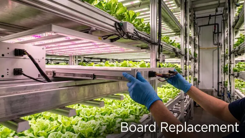
Serviceability is decided at layout, long before anyone needs to replace a board. The following is practical guidance reasoned from rack geometry; published sources on multi-tier service access are thin, so treat it as a design checklist rather than a cited standard.
Connector and harness placement. A module inside a 0.40–0.75 m tier can only be withdrawn toward the aisle. Put the connector on the aisle-facing edge, orient it so the mating half releases without a tool reaching over the LEDs, and leave enough harness slack to bring the module clear of its mounting before disconnecting. Route cables out of the light path and keep them short and guided — a cable lying across the emitting surface is a light loss and a handling hazard (Signify Fortimo design-in guide).
Mounting pattern. Use a hole pattern that lets a single board be released without loosening its neighbors, and keep fastener heads accessible from below. Where boards are butted end to end, a captive-screw or keyhole slot arrangement avoids dropping hardware into the tray below.
Replacement matching. Where several modules share one driver, connect and replace modules from the same series, and preferably the same batch. LED performance improves over time, and mixing efficacies on one driver produces a flux difference between modules. A driver with master and slave modules should be treated as a set.
Service safety. Do not service the system with mains voltage connected — including connecting or disconnecting the cable — and replacement should be performed by an OEM-qualified installer. Where a bare module is used rather than a complete luminaire, the OEM is responsible for the enclosure’s IP classification and approbation; built-in modules carry no IP rating of their own and are not suitable for direct exposure to moisture, dust or chemicals. If condensation can reach the module, the luminaire builder must take precautions to prevent it.
Practical implication for the board specification. Ask for the withdrawal envelope — the distance the module must travel before it clears its fasteners — and confirm it fits the tier clearance with the harness attached. A board that meets every thermal and optical requirement but cannot be removed in place will be removed with the tier, at tier-removal cost.
Weighing Derating Headroom Against Capex
Derating means running the LEDs below their rated current, or specifying a substrate and copper distribution with more thermal capacity than the nominal calculation requires. It buys three things and costs three things.
What headroom buys. A lower junction temperature, which extends projected lumen maintenance; margin against the elevated ambient of a hot upper tier, where the mounting-surface temperature may exceed the assumption behind a nominal design; and tolerance for the difference between a calculated thermal resistance and an assembled one. The efficacy penalty figure cited earlier — 10–20% loss per 10 °C above a 25 °C reference — indicates the direction and rough scale of what headroom protects.
What it costs. A higher substrate tier, more copper, a larger heatsink or interface, and in some cases a larger board that reduces LED density and therefore changes the optical layout. Derating also reduces the PPF available per board, which may mean more boards per tier for the same PPFD target.
The comparison to build. A defensible structure weighs:
- capex per tier, including substrate, copper, heatsink and interface material;
- energy over the service life, at the actual drive current and the facility’s electricity rate;
- replacement labor, which in a multi-tier rack includes access, removal and re-commissioning, not just the module cost;
- the yield risk of PPFD decay late in a fixture’s life, when a crop plan assumes beginning-of-life output.
The weighting among these is a management judgment, not a measured result. What can be measured is the input to the judgment: the in-situ temperature at your drive current and ambient, and the lumen-maintenance projection built from it. A lifetime projection is only as good as the in-situ data behind it — a TM-21 curve built on a case temperature that your tier never reaches describes a different product than the one installed.
Conclusion
A custom board for a vertical farm is defined by the rack it serves. The evidence that it fits is a junction-temperature calculation tied to your drive current and mounting-surface ambient, a stack-up whose dielectric thickness and substrate are justified by your power density, and test data scoped to the assembled luminaire rather than to a component on a laboratory bench.
The decision chain runs in order: establish the design envelope from tier clearance and canopy distance; verify the supplier performed a design rather than a relabel; select substrate and stack-up against power density and isolation; trace the thermal path and agree where board scope ends and fixture scope begins; size traces and clearances to IPC practice; set LED pitch for the near-field regime and verify at canopy level; assemble the documentation set — LM-79, LM-80 with TM-21 within its extrapolation limit, ISTMT, NRTL record, QPL entry; confirm UL 8800 coverage for a US install; plan replacement within the tier clearance; and weigh derating against total cost of ownership using in-situ data.
The practical next step before any purchase order is the documentation request. Ask for the full LM-79 report for the exact model, the LM-80 and TM-21 package with the ISTMT that connects them, the NRTL directory record with model suffix and wet/damp rating, and the current QPL status where a utility program applies. A supplier who can produce that set has shown the design was done; one who cannot has left the question open.
FAQ
How can I tell an engineered board from a relabeled catalog panel?
Ask for four documents: a junction-temperature calculation at your drive current and ambient with each layer’s assumed thermal resistance stated, a stack-up drawing with dielectric thickness, a substrate justification tied to your watts per unit area, and a mechanical outline matched to your mounting pitch. A supplier who cannot state the assumptions behind a thermal figure has not shown the design was performed.
Which substrate fits a given power density, and what changes the answer?
Published selection guidance places standard FR-4 below about 1 W/cm² and aluminum MCPCB above about 2 W/cm², with the middle band a judgment call. The answer shifts with power per LED (aluminum is indicated above roughly 3 W per LED), ambient at the mounting surface (above 30 °C favors metal-core), layer count (four or more favors FR-4), voltage isolation (aluminum MCPCB is listed as suitable below 500 V), and whether the board itself is the heatsink. Reported dielectric conductivity ranges from 1.0–4.0 W/m·K for aluminum MCPCB to 20–30 W/m·K for Al₂O₃ ceramic DBC.
What documentation should I request before a multi-tier approval?
A full LM-79 report for the exact tested model; LM-80 data with a TM-21 projection kept within the method’s stated extrapolation practice; ISTMT data with the temperature measurement point consistent with the LM-80 test point; the NRTL directory record with file number, exact model suffix, voltage, mounting and wet/damp rating; and the current DLC QPL entry where a utility program applies. A QPL listing is not a safety listing, and neither proves yield.
How do I plan replacement without dismantling tiers?
Decide it at layout: connector on the aisle-facing edge, harness slack sufficient to bring the module clear before disconnecting, a mounting pattern that releases one board without disturbing its neighbors, and fastener access from below. Replacement modules should match series and preferably batch where several share a driver. Never service with mains connected, and where a bare module is used, the OEM owns the enclosure’s IP rating.
What do UL 8800 and an NRTL mark actually cover for a US installation?
UL 8800 covers safety for horticultural lighting equipment: elevated-ambient temperature testing at the product’s rated ambient rather than 25 °C, damp location suitability, IP testing, photobiological safety assessment, UV exposure of polymeric materials, and wiring methods that accommodate repositioning. An NRTL mark (UL or ETL) is a third-party safety evaluation with ongoing follow-up; it does not prove light output, yield or rebate eligibility. CE, RoHS, FCC Part 15, and ISO 9001 each have their own scope and do not substitute for it. The AHJ inspects the installation, and the listing supports rather than replaces that inspection.
Where does PCB layout stop and fixture thermal design begin?
The board owns its own stack: die-to-solder, copper, dielectric, base metal, and the board-to-heatsink interface. The rack frame, airflow, plenum, and enclosure belong to luminaire and facility design. The board can lower resistance through its stack; it cannot fix a frame that does not conduct or a tier that recirculates hot air. The supply scope should name which party owns the frame, the interface specification, the airflow assumption, and the ambient used in the calculation.
How should I weigh derating headroom against capex?
Compare capex per tier, energy over service life at the actual drive current, replacement labor including multi-tier access, and the yield risk of PPFD decay late in life. The weighting is a management judgment; the inputs are measurable. Build the comparison on in-situ temperature at your drive current and ambient, because a lumen-maintenance projection based on a case temperature your tier never reaches describes a different product than the one installed.