Introduction
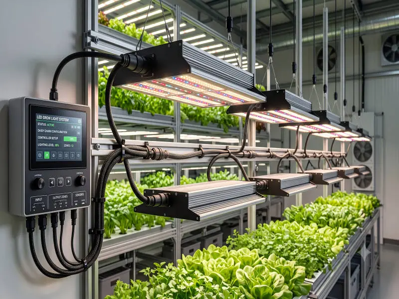
In a commercial cultivation facility, “daisy chaining” can mean two very different things: feed-through power wiring from fixture to fixture and control wiring from device to device. Both can be safe—but only when they’re engineered around listings, load calculations, and a controls topology that won’t create flicker or comms faults.
This guide covers (1) when feed-through wiring is typically permitted, (2) how to size circuits using continuous-load rules of thumb (the practical grow light circuit sizing 80% rule), and (3) how to wire 0–10V and RS-485 controls so they scale across rooms and zones when you’re daisy chaining commercial grow lights.
Use this alongside your local electrical code cycle, your AHJ (Authority Having Jurisdiction) requirements, and the luminaire/controller manufacturer’s installation instructions. When those sources disagree, the listing/labeling and the AHJ’s interpretation win.
Table of Contents
Compliance Foundations
When Feed-through is Permitted
Feed-through (pass-through) wiring is permitted only when the luminaire is listed and labeled for it, and the manufacturer’s installation instructions explicitly allow it. This is the core of commercial LED grow light wiring feed-through: you’re installing a listed wiring method, not inventing one.
In practice, that means:
- The fixture has designated line in / line out terminals or a listed feed-through connector system.
- The manufacturer specifies a maximum pass-through current (or max fixtures per chain) and the allowed conductor sizes/temperature ratings.
- The wiring method and connectors are installed exactly as described—no substitutions, no “close enough” adapters.
⚠️ Warning: Don’t confuse listed feed-through luminaires with the OSHA problem of “daisy chaining” power strips/extension cords. In commercial rooms, inspectors care about listing/labeling, conductor protection, and documentation, not just neat cable runs.
Environment Ratings Selection
Commercial grow rooms are hard on electrical gear: humidity, condensation cycles, nutrient aerosols, and periodic cleaning can turn marginal connectors into chronic failures.
Select fixture and connector ratings based on the real cleaning method (wipe-down vs. spray vs. washdown) and mounting location. A good starting point is your facility’s sanitation SOP, then map that exposure to the fixture’s stated suitability and IP/NEMA protection. For a deeper framework on matching ingress protection to grow-room conditions, see SLTMAKS’ guide to IP rating commercial grow lights.
Documentation for Inspectors
Inspection friction usually comes from missing paperwork, not missing intent. Build a documentation packet that a third party can audit quickly:
- Cut sheets + installation manuals for every luminaire model and every controller
- A one-line electrical diagram showing panels, circuits, disconnects, and zones
- Load calculations (by circuit and by panel) with assumptions stated
- A fixture schedule: model, wattage/nameplate current, quantity, and location/zone
- Photos of labels and field-applied circuit IDs (especially after close-out)
If you’re also relying on rebates or efficiency programs, keep certification evidence easy to retrieve. SLTMAKS notes that DLC (DesignLights Consortium) Hort certification
is often a practical requirement for utility rebate workflows.
Circuit Sizing & Wiring Methods
Load Calculations and 80% Rule
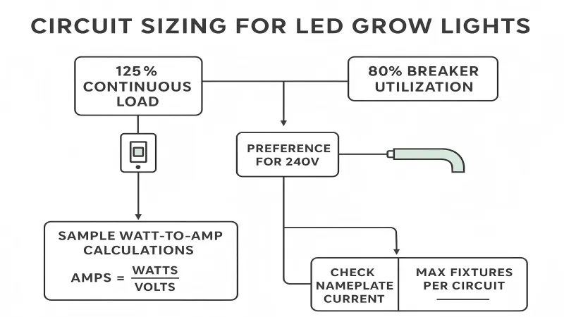
Most commercial grow-lighting runs long enough to be treated as a continuous load (expected to run at maximum current for three hours or more). Electrical code commentary commonly summarizes the implications as:
- Size the breaker (OCPD) at 125% of the continuous load, which produces the field rule of thumb that a standard breaker should be loaded to ~80% for continuous lighting.
- Size branch-circuit conductors to carry 125% of continuous load before applying other adjustments.
For a practical explanation of the continuous-load definition and the 125% sizing concept, Electrical Contractor Magazine outlines it in “Sizing Conductors, Part III”
. For the breaker-side rule-of-thumb, Design Master summarizes the branch-circuit sizing logic in “Sizing Branch Circuits for Continuous & Noncontinuous Load Types”.
Two practical implications for commercial rooms:
- Count nameplate watts/amps, not marketing watts. Use the luminaire nameplate current (or true input watts) for calculations.
- Prefer 240 V where the equipment supports it. For the same wattage, higher voltage reduces current, which increases headroom for conductors, connectors, and pass-through limits.
Example: Max Fixtures per Circuit
Assume these typical planning inputs:
- Fixture input power: 650 W each
- Supply voltage: 240 V
- Branch circuit breaker: 20 A
- Continuous-load allowance on a standard breaker: 16 A (80% of 20 A)
- Convert fixture watts to amps:
- 650 W ÷ 240 V ≈ 2.71 A per fixture
- Apply the continuous-load limit:
- 16 A ÷ 2.71 A ≈ 5 fixtures per 20 A circuit (rounded down)
That’s circuit sizing. Feed-through limits can be lower than the branch-circuit limit. If the manufacturer states a maximum pass-through current (or max fixtures per chain), that becomes the binding constraint—even if your panel math says you have spare capacity.
Conductors, GFCI, Grounding
Three areas drive most of the real-world failures in grow rooms:
- Conductors and terminations: Use conductor types and temperature ratings that match the fixture terminals and ambient conditions. Tighten terminations to the manufacturer’s torque specs and re-check during commissioning.
- GFCI and moisture reality: Grow rooms can be damp in practice. Where GFCI protection is required by code or site policy, validate compatibility with drivers and controls during commissioning to avoid nuisance trips.
- Grounding and bonding: Maintain a continuous equipment grounding path through each luminaire and any listed interconnects. Ground faults in high-humidity spaces don’t just trip breakers—they create intermittent behavior that’s difficult to diagnose later.
For a code-focused walkthrough of conductor sizing and overcurrent protection logic (and why terminals and temperature ratings matter), Mike Holt’s reference on conductor sizing and protection
is a useful refresher.
Controls Architecture at Scale
0–10V Design Limits
0–10V dimming is popular because it’s simple and broadly supported—but it’s also easy to wire in ways that create flicker and low-end instability.
A practical baseline (think 0–10V dimming wiring shielded twisted pair in the field):
- Use a shielded pair for the control run.
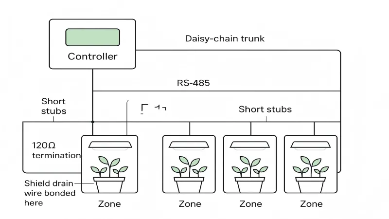
- Bond/ground the shield at the controller end (and avoid bonding both ends unless the manufacturer specifies it).
- Keep control wiring routing disciplined so it doesn’t act like a noise antenna.
Moons Industries summarizes the rationale clearly: 0–10V dimming basics and troubleshooting
notes that unshielded analog control wiring can pick up radiated emissions (motors, transformers, radio sources) that drivers interpret as changes in control voltage—showing up as flicker.
RS-485 Bus Best Practices
When you need reliable multi-zone control across long rooms and many fixtures, RS-485 (often carrying protocols like Modbus RTU or proprietary lighting control) is common because it tolerates distance and noise better than many alternatives—when installed correctly.
Best-practice fundamentals (in other words, RS-485 lighting controls best practices):
- Use a bus topology (daisy-chain trunk), not a star. RS-485 is intended for a line/bus arrangement; star and ring layouts increase reflections and instability.
- Terminate both ends of the bus with resistors that match the cable’s characteristic impedance (commonly 120 Ω for twisted pair).
- Keep stubs short and predictable. Long stubs behave like little antennas and reflection points.
- Plan for a defined idle state (biasing/failsafe) so the line doesn’t float when nothing is actively driving it.
For a plain-language summary of these principles, see the RS-485 standard overview on RS-485
.
Shielding, Bonding, Terminations
In grow facilities, the noise environment isn’t theoretical: VFDs, pumps, dehumidifiers, CO₂ equipment, and long cable trays all add coupling paths.
Practical controls-wiring habits that reduce troubleshooting time:
- Treat control cabling as a designed system: specify cable type (shielded twisted pair), routing, and bonding points.
- Be explicit about where shields are bonded and how grounds are referenced so you don’t create accidental ground loops.
- Document terminations and device addresses/zone assignments at install time, not after something fails.
Applying Daisy Chains Safely
When to Daisy Chain Grow Lights
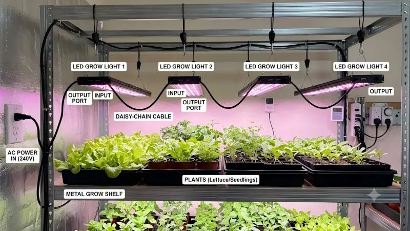
Daisy chaining is usually a good fit when:
- The luminaires are listed for feed-through, and the manufacturer publishes clear limits.
- The run is mechanically clean: strain relief, protected routing, no connectors hanging in the airflow.
- You want modular expansion while keeping circuits and zones easy to label.
- You can keep each chain aligned to one branch circuit and one controls zone.
When Not to Daisy Chain
Avoid daisy chaining (or re-architect it) when:
- Any fixture in the chain is not explicitly approved for pass-through.
- You’re forced into long “spaghetti” stubs, mixed connector families, or uncontrolled routing near noisy power equipment.
- The room layout creates multiple failure blast-radius scenarios (one bad connector darkens a critical aisle).
- You need more isolation for commissioning and uptime (home runs to junction boxes or distributed panels may be the better trade).
Manufacturer Limits & Brand Note
Manufacturer limits are not “suggestions.” They’re typically tied to internal conductor ampacity, connector ratings, thermal rise inside the housing, and listing conditions.
Verify and record:
- Max pass-through current (or max fixtures per chain)
- Allowed interconnect cables/connectors and their ratings
- Permitted conductor sizes and temperature ratings
- Control port limits (how many drivers per 0–10V channel; RS-485 node limits)
SLTMAKS note (educational): SLTMAKS luminaires are designed with UL 8800/1598 suitability, appropriate IP/NEMA options, and documented feed-through/controller limits—always follow the specific cut sheet and installation manual.
Commissioning & QA
Pre-power Checklist
Before energizing, treat commissioning like a safety-critical handoff:
- Lockout/tagout (LOTO) verified; correct circuit identified and labeled
- All fixtures mechanically secured (no load on cords/connectors)
- Terminations torqued to spec; strain relief and glands installed
- Grounding continuity verified end-to-end
- Circuit load calculation attached to the as-built packet
- Controls wiring labeled by zone; shields/terminations installed per design
Controls Verification
Controls issues are cheaper to fix before plants are in the room.
Verify:
- 0–10V: full range dimming behavior (including low-end), correct polarity, no flicker under normal equipment operation
- RS-485: addressing, stable comms across all nodes, proper end-of-line terminations, and predictable behavior when a node is disconnected
If you see flicker or unstable dimming, don’t guess. The Moons Industries 0–10V dimming basics and troubleshooting guide includes a simple isolate-the-problem flow that can save hours.
Ongoing Maintenance Cadence
Daisy chains are maintainable when you plan for it:
- Quarterly: visual inspection of connectors, glands, and cable routing in high-moisture areas
- Semi-annually: spot-check torque on accessible terminations during a planned downtime window
- Annually: validate dimming uniformity and zone mapping against current crop plans; update as-built docs when fixtures move
Conclusion
Safe daisy chaining at commercial scale comes down to three habits: treat feed-through as a listed feature (not a convenience), size circuits as continuous loads, and design controls wiring like a real network—with shielding, topology, and verification steps that match the facility’s noise environment.
Keep the process audit-friendly: verify manufacturer listings/limits, coordinate early with the NEC/AHJ, and maintain an as-built documentation package that makes future expansions and inspections predictable.
FAQ
How many commercial LED grow lights can I daisy-chain on a single 20A circuit at 240V?
Start with the continuous-load rule of thumb: a 20A breaker is typically planned at 16A usable load (80%) for lighting that runs 3+ hours. Convert each fixture’s input watts to amps (A = W ÷ V). For example, a 650W fixture at 240V draws ~2.71A, so 16A ÷ 2.71A ≈ 5 fixtures per 20A circuit (rounded down).
Important: the manufacturer’s feed-through limit (max pass-through current or max fixtures per chain) can be lower than your circuit math—always follow the listing/label instructions.
Is daisy chaining grow lights safe and code-compliant in a commercial facility?
It can be safe only if the fixture is listed and labeled for feed-through (pass-through) wiring and you follow the manufacturer’s installation instructions exactly (connectors, cable type, conductor size/temperature rating, and maximum pass-through current). In commercial rooms, inspectors typically focus on listing/labeling, load calculations, grounding/bonding continuity, and documentation (cut sheets, one-line diagram, fixture schedule, and as-built photos).
What’s the difference between daisy chaining power and daisy chaining control cables (0–10V or RS-485)?
“Daisy chaining” can mean two different systems:
1. Power feed-through: Line voltage is passed fixture-to-fixture using approved line-in/line-out terminals or listed interconnects, with a strict max pass-through rating.
2. Controls daisy chain: Low-voltage signal wiring runs device-to-device.
– 0–10V is analog; it’s simple but more sensitive to noise and grounding mistakes.
– RS-485 is digital multidrop; it scales better for long runs and many fixtures if you use a true bus topology and proper termination.
How do I wire 0–10V dimming to prevent flicker in a grow room?
Use shielded twisted pair for the control run, keep control wiring away from noisy power equipment when possible, and bond the shield at the controller end (avoid bonding both ends unless your controller/driver documentation explicitly says to). Also confirm polarity and test low-end dimming behavior during commissioning. Grow rooms often have real noise sources (VFDs, pumps, dehumidifiers), so good cable choice and routing discipline matter.
What’s the correct RS-485 daisy chain wiring for commercial lighting controls?
RS-485 should be wired as a bus (trunk) topology, not a star. Best practice is to terminate both ends of the bus with resistors that match the cable impedance (commonly 120Ω), keep stubs short, and ensure the network has a stable idle state (biasing/failsafe, depending on the controller). Label addresses and document terminations during installation—most “random” comms failures come from topology and termination mistakes.