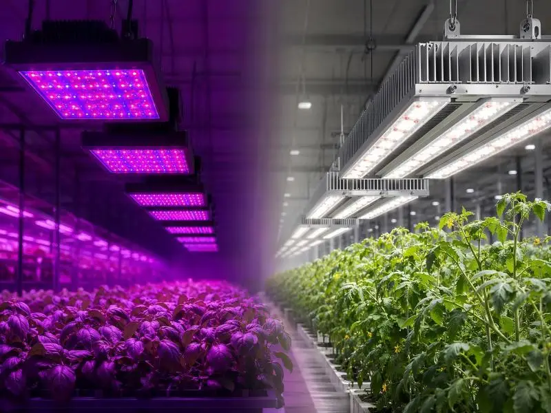
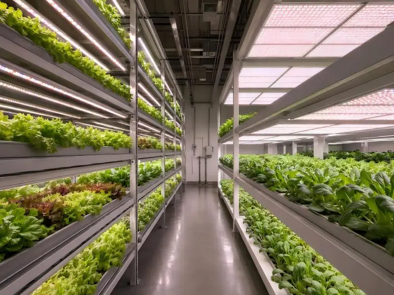
When approaching vertical farming LED sourcing, a procurement team rarely chooses between two brands. It chooses between two geometries. A linear bar and a broad panel can carry the same diodes, the same efficacy class, and the same listing, yet behave differently once they are bolted into a rack with 0.40–0.75 m of clear tier height and a canopy sitting 0.15–0.40 m below the light surface. The form factor sets how the light spreads across a tray, where the heat goes, how a technician reaches a failed unit, and how much copper and conduit the electrical package requires.
This article evaluates both designs against the same criteria rather than declaring a winner. The sequence follows the order a sourcing decision actually resolves: rack geometry and photometry first, because those eliminate options fastest; then thermal load and airflow; then US listing and performance documentation; then controls and driver placement; then serviceability and downtime exposure; and finally a total-cost-of-ownership (TCO) structure that puts both geometries on equal terms. Where a criterion favors one shape, the condition under which it does is stated with it.
Table of Contents
Bar vs. Panel at a Glance: A Guide to Vertical Farming LED Sourcing
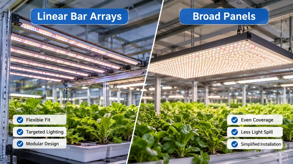
The matrix below is a directional summary of typical behavior. Individual products can outperform or underperform their form factor’s profile — a well-engineered panel can beat a poorly engineered bar on uniformity, and a bar array can be specified badly enough to lose on serviceability. Treat each cell as a question to verify against submitted data, not a verdict.
| Criterion | Linear bar arrays | Broad panels |
|---|---|---|
| Fit to rack geometry | Strong where tray width and tier depth are known and bars can be spaced to the tray; flexible across odd bay dimensions | Strong where the panel footprint matches a standard tray and tiers are deep enough to accept a single wide body |
| Uniformity at close mounting | Depends on bar spacing and beam profile; achievable but must be modeled per tier | Typically easier to make even across a rectangular tray from one body; edge falloff still needs data |
| Stray light and aisle spill | More spill at tray edges unless optics or reflectors control it | Less edge spill where the panel covers the tray; more blocking of vertical airflow |
| Photometric comparability | Often tested as a single unit; multi-bar systems need system-level data | Usually tested as one luminaire; data maps more directly to the installed body |
| Heat rejection into the space | Distributed across the tier; drivers may be onboard or remote | Concentrated in one footprint; often paired with remote or centralized drivers |
| Airflow through canopy | Leaves gaps between bars for vertical air movement | Covers the canopy; depends on fan-assisted or ducted air paths |
| Listing and documentation | Same UL 8800 and DLC framework; DC-powered bar systems carry extra controllability requirements | Same framework; larger single luminaire simplifies some submittals |
| Serviceability | Replace one bar or one driver; finer replacement granularity | Replace a larger assembly; fewer units but higher cost per event |
| TCO sensitivity | Sensitive to bar count, mounting labor and driver architecture | Sensitive to HVAC interaction and replacement cost per failure |
Read the matrix as a map of where to demand evidence. The sections that follow explain why each row behaves as it does and what documentation settles it.
Rack Geometry and Tier Spacing
Vertical racks impose a constraint that greenhouse and warehouse lighting does not: the mounting distance is fixed by the building, not chosen by the designer. Published design guidance for vertical-farm LED modules describes typical clear height between the growing surface and the underside of the tier above at roughly 0.40–0.75 m, with the LED surface sitting 0.15–0.40 m above the canopy depending on crop stage and mounting position. At those distances, there is no room for the beam to blend. Whatever pattern leaves the fixture arrives at the tray largely intact.
That changes which photometric problem governs. In a high-bay installation, the concern is reaching the floor at target intensity. In a rack, the concern is uniformity across the tray and containment of light that would otherwise escape into aisles, onto neighboring tiers, or onto workers. A study of choy sum seedlings in indoor farm racks illustrates the scale of the loss: under reflector-free control, photosynthetic photon flux density (PPFD) across a shelf ranged from 119.6 to 265.8 μmol/(m²·s), and adding an adjustable reflector narrowed that spread substantially by recovering light at the shelf margins. The lesson for sourcing is that edge performance is a design property of the fixture-plus-rack system, not an afterthought.
Bars map naturally onto racks whose tray width and tier depth are already fixed. Because they are narrow, they can be spaced to the tray, run the length of a bay, and leave gaps for vertical air movement. The trade-off is that uniformity becomes a function of bar count, spacing, and beam angle, which means the supplier must model the array for the actual tier rather than quoting a single-bar photometric file.
Panels map naturally onto racks built around a standard tray module, where one body covers the growing area and edge falloff is contained by the housing. A panel remains the sensible choice when tiers are deep enough to accept a wide body, when the tray is a single rectangular module, and when the crop plan does not call for frequent reconfiguration of bar positions.
The rack conditions to settle before comparing products in vertical farming LED sourcing: clear height per tier, tray width and length, aisle width, whether trays are fixed or sliding, and whether the crop plan changes by season. A bar array specified for a fixed tray can become a liability if the operation later switches to a wider tray; a panel specified for a narrow tray wastes light and blocks access.
Photometric Data and Fair Comparison at Mounting Height
Two fixtures cannot be compared until their photometric data describe the same measurement conditions. The DLC’s horticultural technical requirements anchor this: testing is conducted at accredited laboratories using ANSI/IES LM-79-19 for photometric and electrical performance, with in-situ temperature measurement testing (ISTMT) supporting thermal claims. LM-79, as the US Department of Energy’s guide explains, is a snapshot of performance under specified operating conditions at a point in the product’s life, usually at the start. It does not address lifetime ratings or performance over time, and it applies to integrated products such as luminaires, not to bare LED packages or arrays.
The metrics that matter for sourcing:
- Photosynthetic photon efficacy (PPE), in μmol per joule, which is the metric the DLC thresholds govern. Hort V4.0, effective April 18, 2025, sets a minimum of 2.5 μmol·J⁻¹, an 8.7% increase over V3.0, with a −5% tolerance in evaluation, meaning test reports at 2.38 μmol·J⁻¹ or above are accepted. The DLC states this threshold sits more than 45% above the most efficacious non-LED option, a 1000 W double-ended high-pressure sodium luminaire.
- PPFD distribution across the tray, not a single center-point value. Ask for a grid map at the actual mounting distance, with minimum, average, and the min/avg ratio stated.
- Beam and intensity distribution data, ideally as an ANSI/IES TM-33 file. The DLC requires TM-33 documents with specific header, luminaire, and emitter fields, and explicitly does not accept intensity scaling relative to laboratory measurements.
- Spectral data, including whether far-red output is present and how it is reported. The DLC requires photon intensity and photon flux fields to carry only PPF (400–700 nm) data, and requires Q90 reporting for the 700–800 nm far-red range without qualifying on it.
The comparison trap is mounting height. A bar tested at 0.6 m and a panel tested at 0.3 m produce numbers that cannot be placed side by side. Before ranking anything, confirm that both datasets were generated at the same distance from the light surface to the measurement plane, at the same input voltage, at the same dimming setting, and with the same photometric apparatus. DOE’s LM-79 guidance notes that integrating-sphere and goniophotometer methods capture different information — a sphere-only report will not characterize spatial distribution, and a goniophotometer-only report is unlikely to include color metrics. A supplier who cannot say which method produced the file has not yet supplied comparable data.
For multi-bar systems, request system-level photometry for the array as installed, not just a single bar. The DLC’s DC-powered product provisions anticipate exactly this architecture: because DC-powered products are often designed so that multiple light bars combine into a larger light source, all DC-powered products must be dimmable regardless of photon flux.
Thermal Load, HVAC and Airflow
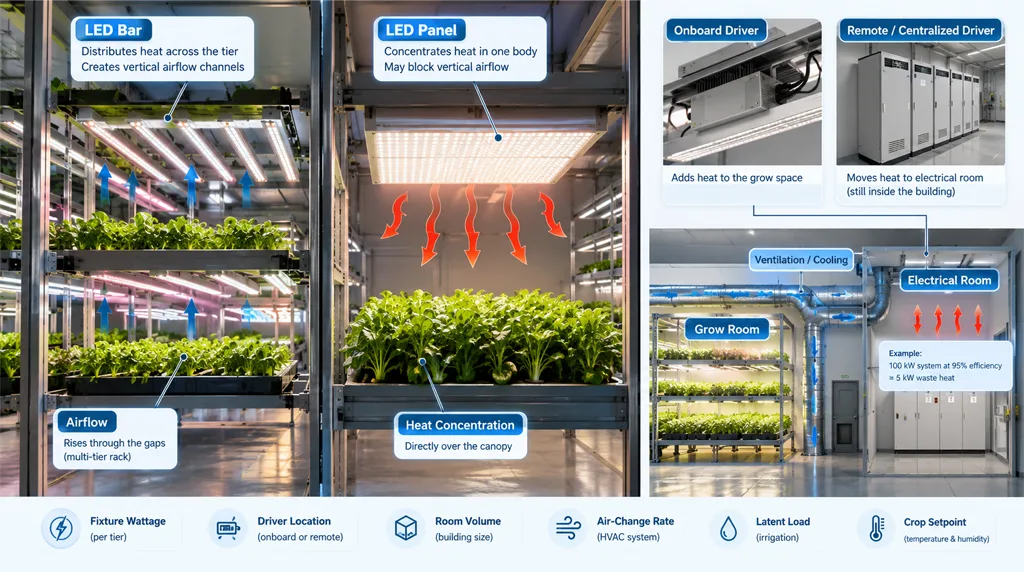
Every watt delivered to the diodes leaves the fixture as heat, and in a sealed grow room that heat becomes an HVAC load. The form factor changes where the heat enters the space and how air moves past the canopy.
Bars distribute heat across the tier. Because they are narrow and spaced apart, they leave vertical channels through which air can rise or be drawn, which matters in multi-tier racks where buoyancy and mechanical ventilation both act over short distances. Panels concentrate heat in one broad body that sits directly over the canopy, and a solid panel can act as a barrier to vertical airflow unless the facility design provides a path around it or the fixture uses onboard fans.
The driver is the second heat source, and its location is a specification decision. Onboard drivers add their losses to the grow space. Remote or centralized drivers move that heat to an electrical room — but not out of the building. A centralized cabinet for a 100 kW system operating at 95% efficiency still produces roughly 5 kW of waste heat inside that room, as one supplier’s technical guidance notes, so the electrical room needs ventilation or supplemental cooling of its own. Moving drivers out of the grow room relocates the thermal problem; it does not delete it.
Quantitative claims in this area deserve scrutiny. Vendor statements about grow-room temperature reduction from centralized drivers are typically facility-specific and should be treated as hypotheses to test in an energy model, not as design inputs. The buyer’s job during vertical farming LED sourcing is to model the HVAC interaction for their own building: fixture wattage per tier, driver location, room volume, air-change rate, latent load from irrigation, and the setpoint the crop plan requires. A form factor that looks efficient on a datasheet can still drive a larger air-handling package if it blocks airflow or concentrates heat where the return is weakest.
Certification and Documentation for US Installations
US installations are governed by a code-and-listing framework that applies regardless of fixture shape. The 2020 National Electrical Code, Article 410, Part XVI addresses horticultural lighting specifically, requiring equipment identified for horticultural use to be listed, grounded per Article 250, and installed only where it is not likely to be subject to physical damage or concealed. Where the space is a hazardous (classified) location, Articles 500 through 517 apply in addition.
DLC Horticultural Technical Requirements V4.0, released 2025-03-12, effective 2025-04-18, revised 2025-10-01. These are DLC QPL eligibility thresholds, not electrical code compliance requirements; UL 8800 listing is a separate requirement. The PPE threshold carries a −5% absolute tolerance in evaluation, so test reports at 2.38 μmol·J⁻¹ or above are accepted, while nominal reported values must be at or above 2.5 μmol·J⁻¹.
The listing standard is UL 8800, Standard for Safety for Horticultural Lighting Equipment. UL describes it as the first set of standardized requirements designed specifically for horticultural lighting, introduced in 2017, and it differs from the general luminaire standard UL 1598 in ways that matter for a vertical farm: photobiological safety consistent with IEC 62471, wiring and connection methods that allow fixtures to be raised, lowered, or repositioned, evaluation for damp and wet environments and elevated ambient temperatures, ingress protection (IP) ratings, and UV exposure requirements for polymeric materials. UL lists horticultural luminaires under the product category IFAU and complete horticultural lighting systems under HRTI.
The performance qualification layer is the DLC Horticultural Qualified Products List (QPL). Hort V4.0 requires, among other thresholds, photon flux maintenance Q90 of at least 36,000 hours demonstrated through LM-80 and TM-21 (or LM-84 and TM-28), driver lifetime of at least 50,000 hours, fan lifetime of at least 50,000 hours at an operating temperature at or above the fixture’s highest rated ambient, a fixture warranty of at least five years covering the complete luminaire, power factor of at least 0.9, and total harmonic distortion of 20% or less.
The DLC notes that the V3.0 QPL had an update deadline of October 31, 2025, and a delist date of January 5, 2026, so a supplier citing a V3.0 listing today should be asked to confirm the product’s current V4.0 status.
Form factor does not change the compliance burden in principle — a bar and a panel are both luminaires, and both need the same listing and the same performance documentation. It does change the submittal in practice. A DC-powered multi-bar system carries the DLC’s additional controllability requirements, and a system that combines bars with a central power source needs documentation for the power source as well as the bars. A single panel is a simpler submittal, but only if its driver and fan documentation is complete.
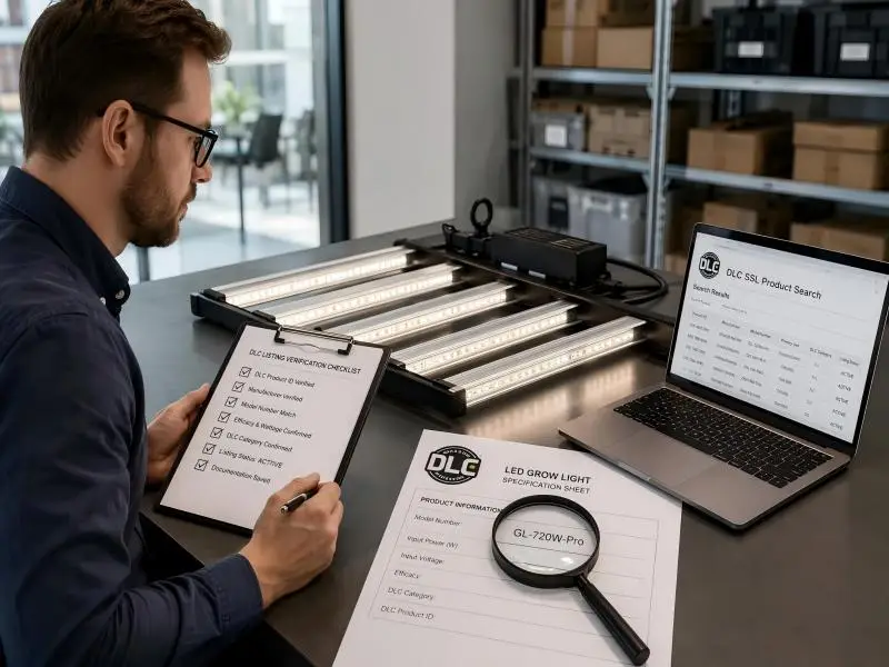
A supplier questionnaire for US procurement should ask for: the UL 8800 listing certificate and the product category under which it is listed; the DLC QPL listing identifier and current version; the LM-79 report with laboratory accreditation, test date and apparatus; the TM-33 file; LM-80 and TM-21 (or LM-84 and TM-28) reports with the projection temperature basis; ISTMT results; driver and fan specification sheets with lifetime and reference operating temperature; the full warranty terms; and, for DC-powered products, the DC cabling specifications and guidance for keeping cabling losses below 2% for a fully loaded power supply.
Controls, Driver Placement and Power Distribution
Dimming is where specification language earns its keep. The 0–10 V interface remains the most common luminaire control option because it is inexpensive and simple, but a study of 0–10 V dimming across LED luminaires found that the interpretation of the control signal varies widely between products. In the study’s sample, relative power draw across different make and model luminaires ranged by roughly 46 percentage points on average across control voltages, while unit-to-unit variation within the same model was much smaller — about 4 percentage points in the sample tested. Two luminaires using the same make and model driver produced different dimming curves because the connected load differed.
The practical consequence for a vertical farm is that a dimming schedule written as a percentage will not deliver the same light level across a mixed fixture population. Specify the dimming curve, the minimum dim level, whether the driver supports dim-to-off, and the tested relationship between control voltage and relative output — and require that the curve be verified at the fixture level, not just the driver datasheet. The DLC’s controllability requirements for horticultural products capture dimming capability in the listing, which gives procurement a checkable field.
Driver placement is the second controls decision. Onboard drivers simplify wiring at the fixture and keep DC runs short, but they put heat in the grow space and require access at canopy height for replacement. Remote or centralized drivers move the electronics to a cabinet, which can simplify maintenance and reduce heat around the canopy, at the cost of longer DC runs, a dedicated electrical room, and a single point of failure unless the platform is modular. Centralized platforms with MODBUS or similar communication can report power draw, module temperature, operating hours, and fault codes to the facility’s environmental controller, which is a genuine operational advantage in a multi-tier facility.
Specification language that translates these differences: state the dimming protocol and curve, the minimum dim level, the driver location, the maximum ambient temperature at the driver, the DC cable gauge and length limits with the associated loss calculation, the control interface to the facility controller, and the monitoring data the platform must expose. For bars, also state whether the array is powered by a single central supply and how many bars share it, because that determines both the failure domain and the cabling design.
Serviceability, Spares and Downtime Risk
In a multi-tier rack, a failed fixture is not just a parts cost. The tier below it loses light for the duration of the outage, and if the crop is on a fixed harvest schedule, the loss is measured in delayed or reduced yield, not in the price of a driver.
The form factors differ in replacement granularity. A bar array lets a technician replace one bar or one driver without removing the whole lighting layer, and the remaining bars keep producing. A panel is a larger assembly; a failure may take out a wider swath of the tray at once, and the replacement is heavier and more awkward to handle at height. The counterargument is unit count: a panel installation has fewer bodies to monitor and fewer connections to fail, which can reduce the number of service events even if each event is larger.
Access is the deciding variable. Ask how a technician reaches the fixture in the installed rack: is there clearance above the tier, can the tray be slid out, does the fixture hinge or slide, and does the replacement require a second person? A design that is easy to service on a bench can be difficult to service at 2 m in a narrow aisle.
Spares strategy follows from the failure domain. For bars, the sensible spares kit is a small number of bars plus the drivers and any central power modules, sized to the number of bars per tier and the lead time. For panels, the kit is a small number of complete luminaires plus drivers. In both cases, ask the supplier for the documented lifetime basis for drivers and fans — the DLC requires driver and fan lifetimes of at least 50,000 hours with a reference operating temperature — and for the field-replaceable component list. A supplier who cannot say which components are field-replaceable and which require a factory return has not yet answered the downtime question.
The service questions to settle before signing: mean time to replace a bar, a panel, a driver and a fan; whether replacements are stocked in the region; the lead time for a spare; whether the warranty covers labor and re-commissioning or only the component; and what monitoring the fixture or platform provides so a failure is detected before the crop shows it.
Building the TCO Comparison
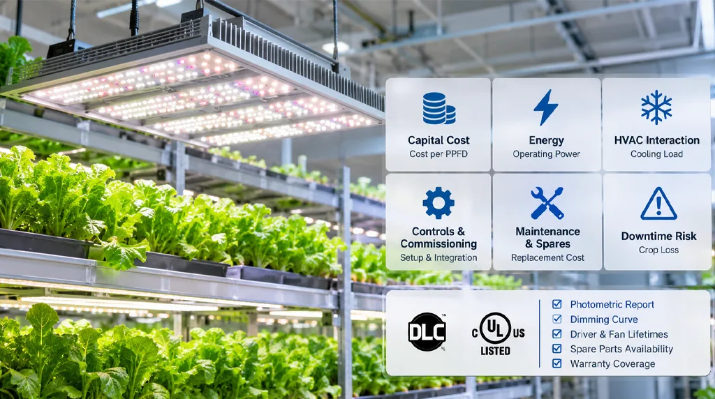
A TCO comparison within vertical farming LED sourcing is only fair if both options are costed over the same life, at the same light level, with the same boundary. The structure below is a framework, not a set of figures — the inputs must come from the supplier’s submittals and the facility’s own energy model.
Illustrative arithmetic only, not a measured finding. Assumes a 300 W fixture operating 18 h/day, 365 days, with essentially all input power rejected as heat inside the conditioned zone (3.412 Btu per watt-hour). Substitute the supplier’s tested wattage at the scheduled dim level and the facility’s own operating hours; driver location changes where the heat lands, not whether it must be removed.
Capital cost. Fixture price per unit, multiplied by the number of units required to hit the target PPFD across the tray at the actual mounting distance. A bar array and a panel rarely reach the same target with the same unit count, so compare cost per unit of delivered photosynthetic photon flux at the tray, not cost per fixture.
Energy. Fixture wattage at the operating dim level, multiplied by operating hours and the local electricity rate. Use the tested wattage at the scheduled dim setting, not the maximum rating, and account for the dimming-curve variability described earlier.
HVAC interaction. The heat rejected into the grow space, plus the heat rejected into the electrical room if drivers are centralized, translates into cooling and ventilation capacity through the facility’s own model. This is where panels and bars can diverge most, and where vendor claims should be replaced by a modeled load.
Controls and commissioning. Controller hardware, wiring, the labor to commission dimming schedules and verify curves at the fixture level, and the cost of integrating with the facility’s environmental controller.
Maintenance and spares. Expected replacement events over the life, based on the documented driver and fan lifetimes and the warranty terms, multiplied by the cost of the part and the labor to replace it at height. Include the carrying cost of the spares kit.
Downtime risk. The expected crop loss per failure event, multiplied by the expected number of events and the time to restore light. This is the line most often omitted and the one that can change the ranking.
The acceptance criteria that convert the analysis into a purchase decision: a photometric file at the actual mounting distance showing min/avg PPFD at or above the crop plan’s requirement; a current DLC V4.0 listing and a UL 8800 certificate; a dimming curve verified at the fixture level; documented driver and fan lifetimes with reference temperatures; a field-replaceable component list with regional spare stock; and a warranty that states what it covers. A supplier who meets these criteria on paper and can demonstrate them on a sample tier is a lower-risk choice than one who wins on capital cost alone.
Which Design Fits Which Operation
The form factor follows from the operation, not the other way around.
Bars tend to win when: the rack has fixed tray dimensions, and the array can be spaced to the tray; tier height is tight and vertical airflow matters; the crop plan calls for reconfiguring light positions between cycles; the facility wants fine replacement granularity and a small spares kit; and the electrical design can support a central power supply with the associated DC cabling documentation.
Panels tend to win when: the rack is built around a standard tray module that matches the panel footprint; tiers are deep enough to accept a wide body; the operation wants fewer connections and a simpler submittal; the facility can provide remote or centralized driver space and ventilation; and the crop plan is stable enough that reconfiguring light positions is not a routine need.
What the outcome depends on: the actual mounting distance and tray geometry, the crop plan’s uniformity requirement, the facility’s HVAC model, the local AHJ’s documentation expectations, and the supplier’s ability to provide system-level photometry and field-replaceable components. Two operations with the same crop can reach different answers if their rack dimensions or electrical rooms differ. The recommendation is to specify the criteria, run the comparison on both geometries, and let the data decide.
Verdict
The form factor is downstream of three things: rack geometry, crop plan and documentation quality. A bar array and a panel can both meet a US installation’s listing and performance requirements; what separates them is how well each maps onto the tier it will serve and how completely the supplier documents the result. The strongest sourcing position is the one that specifies measurable criteria — PPFD distribution at the actual mounting distance, a current DLC V4.0 listing, a UL 8800 certificate, a verified dimming curve, documented driver and fan lifetimes, and a field-replaceable component list — rather than a product shape. Choose the geometry that fits the rack, then hold both candidates to the same evidence standard.
FAQ
Does form factor affect certification burden during vertical farming LED sourcing?
Not in principle. A bar and a panel are both luminaires and both require a UL 8800 listing and, if the buyer wants performance qualification, a current DLC Hort V4.0 listing. In practice, a DC-powered multi-bar system carries additional DLC controllability requirements and needs documentation for its central power source, while a single panel is a simpler submittal. The burden difference is in the paperwork, not the standard.
How do I compare efficacy claims across mounting heights when executing vertical farming LED sourcing?
You cannot, directly. PPE is a fixture-level metric measured under specified conditions, but PPFD at the tray depends on mounting distance and beam distribution. Ask for PPFD grid data at your actual mounting distance, generated at the same input voltage and dim setting, and compare min/avg ratios and delivered flux at the tray rather than headline efficacy alone.
What should I ask suppliers about driver and fan lifetime documentation during vertical farming LED sourcing?
Ask for the driver and fan specification sheets with the stated lifetime and the reference operating temperature for that claim, the ISTMT results, and the LM-80 and TM-21 (or LM-84 and TM-28) reports with the projection temperature basis. The DLC requires driver and fan lifetimes of at least 50,000 hours, with fan lifetime stated at an operating temperature at or above the fixture’s highest rated ambient temperature.
Is a V3.0 DLC listing still acceptable for vertical farming LED sourcing projects?
Check the current status. Hort V4.0 became effective April 18, 2025, and the DLC set an October 31, 2025 update deadline for V3.0 products with a January 5, 2026 delist date. A supplier citing a V3.0 listing should confirm the product’s V4.0 status before it is specified.
Do bars or panels need more maintenance in vertical farming LED sourcing?
It depends on unit count and replacement granularity, not on the shape alone. Bars allow finer replacement but have more connections; panels have fewer bodies but larger replacement events. The deciding questions are access at the installed tier, the field-replaceable component list, and regional spare stock.