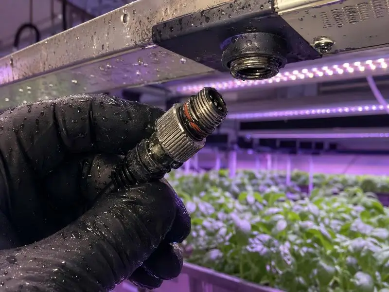
A grow-light connector is not a catalog line item. In a cultivation room, waterproof LED connectors are the part of the lighting circuit that gets unplugged most often, sprayed most often, and re-terminated most often — and they are usually the last component anyone models thermally. That is why connector selection fails in the field more often than in the specification: the catalog rating was read as an absolute, the IP number was read as a promise, and the seal compound was never checked against what the cleaning crew actually sprays.
This guide covers M16 and M19 screw-locking circular waterproof LED connectors used on horticultural fixtures and harnesses, written for facility engineers, integrators, and procurement leads who specify or approve assemblies. It moves in the order a specification actually gets built: what the two designations mean, how to choose an IP rating from the cleaning regimen rather than the marketing sheet, how to derate current for the real thermal environment, how to match seal and housing materials to the chemical list, how to assemble for torque and strain relief, what to test at goods-in and after installation, and where the connector sits in the UL 8800 / NRTL / AHJ compliance chain.
Standards editions, listings, and product families change. The references here are current as of November 2026; verify the edition in force and the specific listing before you commit a facility standard.
Table of Contents
What M16 and M19 Waterproof LED Connectors Actually Are — and What They Are Not
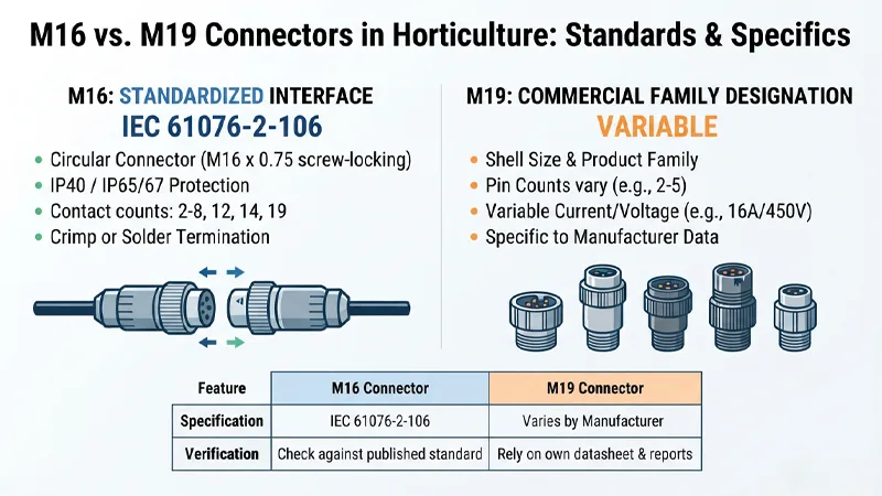
“M16” and “M19” are used loosely in the horticultural supply chain, and the looseness has a cost: one of these designations can be checked against a published standard, and the other generally cannot.
M16 is a standardized interface. IEC 61076-2-106 is the detailed specification for circular connectors with M16 × 0.75 screw-locking and a degree of protection of IP40 or IP65/67. Its scope covers fixed and free connectors, rewireable or non-rewireable, with male contacts of 1.5 mm or 1.0 mm diameter, and it defines contact counts of 2 to 8, 12, 14, and 19, with crimp or solder termination (other termination types by agreement). That gives a specifier something to hold a supplier to: contact resistance, insulation resistance, voltage proof, current-carrying capacity, mechanical operation, and IP degree are all characteristics the detail specification addresses.
M19 is, in most horticultural catalogs, a commercial family designation. It describes a shell or thread size and a product family, not a single IEC detail specification. Representative M19 products illustrate the range of what the label can cover: one published M19 male/female connector lists 2–5 pins, solder or screw wiring, PA66 housing, 20 A/16 A and 450 V ratings, and IP68; a related M19MF data sheet lists 450 V, 20 A on 2/3 pins and 16 A on 4/5 pins, wire sections of 0.5–2.5 mm² (2/3 pins) and 0.5–1.5 mm² (4/5 pins), cable acceptance of 3.5–7 mm, 5–8 mm or 7–10 mm depending on gland, 1500 insertion cycles, and a −40 °C to +105 °C range.
None of that is wrong — it is simply product-specific, and it must be judged as such.
The practical consequence is a difference in verification method. An M16 part can be compared against a published IEC scope and its declared characteristics checked for consistency with that scope. An M19 part must be judged on its own datasheet, its own test reports, and its own listing or recognition, because there is no shared detailed specification to fall back on.
| Attribute | What to compare | Why it matters on a grow-light installation |
|---|---|---|
| Shell/coupling diameter | Mated envelope and clearance to fixture and trellis | Determines whether the assembly fits and whether the coupling nut can be gripped |
| Contact count and termination | 2–19 contacts; crimp, solder or screw | Field re-termination method must match the skill level on site |
| Current / voltage rating | Rating and the conditions it was established under | A catalog current is conditional — see the derating section |
| Mating cycles | Declared mechanical operations | Fixtures are raised, lowered, and re-lamped repeatedly |
| Cable acceptance | Jacket diameter range and gland options | The most common assembly error is a gland that does not match the jacket |
Do not assume a larger shell means more current or better sealing. Shell size sets the envelope and the contact layout; current capacity depends on contact system, conductor, and thermal path, and sealing depends on the seal design and the mated condition. A 19 mm coupling ring appears on products rated at 8 A and 250 V in one family and on products rated far higher in another. Read the rating, not the diameter.
Which IP Rating a Cultivation Room Actually Requires
IP selection should start from the second characteristic numeral’s definitions in IEC 60529, not from a supplier’s shorthand. The standard defines the numerals as follows: 3 — water sprayed at an angle up to 60° on either side of the vertical; 4 — water splashed against the enclosure from any direction; 5 — water projected in jets from any direction; 6 — water projected in powerful jets from any direction; 7 — temporary immersion under standardized conditions of pressure and time; 8 — continuous immersion under conditions agreed between manufacturer and user, more severe than numeral 7; 9 — water projected at high pressure and high temperature from any direction.
Test conditions for the IEC 60529 second characteristic numerals most relevant to grow-room connectors. Numeral 8 has no fixed depth or duration — it is agreed between manufacturer and user, so an unqualified IP68 claim cannot be made. Numerals 3–6 are fresh-water tests; the standard states protection may not be satisfactory where high-pressure, high-temperature cleaning or solvents are used outside numeral 9.
The test conditions behind those words are specific. Numeral 5 uses a 6.3 mm nozzle at 12.5 L/min ± 5%, numeral 6 a 12.5 mm nozzle at 100 L/min ± 5%, both at 2.5–3 m distance, for 1 min/m² and at least 3 min. Numeral 7 immerses the enclosure for 30 min with defined water levels (for enclosures under 850 mm tall, the lowest point 1000 mm below the surface; for taller enclosures, the highest point 150 mm below the surface) and with the water temperature within 5 K of the equipment. Numeral 8’s depth and duration are by agreement — which is why an unqualified IP68 claim carries no usable information.
What the IP code does not cover. IEC 60529 states that the tests for the second characteristic numeral are carried out with fresh water, and that actual protection may not be satisfactory if cleaning operations use high-pressure and high-temperature water jets outside the requirements of numeral 9, and/or solvents. The standard’s scope also places mechanical impacts, corrosion, corrosive solvents, fungus, vermin, solar radiation, icing, moisture produced by condensation, and explosive atmospheres outside the IP code — those are matters for the relevant product standard.
For a grow room, that list is not boilerplate. Condensation on a fixture that cycles hot and cold, nutrient salt residue, and peroxide or hypochlorous acid sanitizers are exactly the exposures the IP code declines to rate.
Translating to cultivation scenarios:
- Overhead spray and fogging. Directional spray and splash dominate; numeral 4 is the floor, and a connector mounted where it receives direct jetting from a hose needs 5 or 6.
- Drip and splash at bench level. Numeral 4 covers splash from any direction, but a connector lying in a puddle is an immersion question, not a splash question.
- Pressure-washer washdown. Numeral 6 at minimum, and only if the washer’s actual pressure, temperature, and nozzle are within the numeral 6 test envelope. A hot high-pressure washer is a numeral 9 exposure, and most circular connectors are not rated for it.
- Condensation. Not an IP test at all. A sealed connector that breathes through a poorly made gland will accumulate water regardless of its numeral.
Two rules follow. First, for most circular connectors the IP rating is a mated-condition rating — an unmated plug needs a sealing cap to maintain it, which is why connector families sell caps specifically for that purpose. Second, an IP68 datasheet entry means nothing specific unless depth and duration are stated; where a manufacturer does state them, that is the number to design to. The M16 detail specification’s own scope — IP40 or IP65/67 — is a useful example of a standard bounding the claim rather than letting the numeral float free.
How to Derate Current for Conductor Size, Ambient Temperature and Duty Cycle
A connector’s published current is a conditional value, not a universal maximum. It was established under a specific test configuration, at a defined ambient, with a defined temperature-rise endpoint and a defined number of energized contacts. Derating is the engineering step that converts that catalog number into an application-specific allowable current.
The underlying logic is a temperature budget. The upper limit temperature of a component is set by its materials. The sum of ambient temperature plus the temperature rise caused by current load — the resistive loss in contacts and conductors — may not exceed that limit, or the component is damaged. Because the rise is roughly proportional to I²R, the allowable current falls as ambient rises. That is why a derating curve slopes downward toward the component’s upper limit temperature.
Weidmüller’s explanation of the derating curve is a clean model of how such a curve is produced: component temperatures and ambient temperatures are measured at three different currents, the temperature rises are plotted against ambient, the points are joined into a base curve, and the curve is then reduced — Weidmüller reduces currents to 80% — to account for maximum permissible volume resistances and measurement uncertainty. Where the derating curve exceeds what the connected conductor cross-section can carry at low ambient, the curve is limited to the smaller current. Two things follow for a specifier: the curve already contains a conductor limit, and it is an all-conditions document, not a single number.
The test method is standardized. IEC 60512-5-2 (Test 5b, current-temperature derating) is the method for assessing current-carrying capacity at elevated ambient temperature, so a supplier publishing a derated curve should be able to say it was produced that way rather than extrapolated from a single rating.
The levers a grow-light designer actually controls:
- Conductor cross-section. The connector’s rated wire range caps current independently of the contact. An M19 product rated 20 A on 2/3 pins accepts 0.5–2.5 mm² on those pins but only 0.5–1.5 mm² on 4/5 pins, where the rating drops to 16 A. The wire range and the current rating move together; specifying one without the other is incomplete.
- Contact loading. A single-contact rating does not describe a fully loaded connector. More energized contacts mean more thermal coupling. Ask for the all-contacts-loaded curve.
- Duty cycle and dimming schedule. A fixture at full output for 12 hours a day sits at a different steady state than one dimmed through a photoperiod schedule. The thermal endpoint that matters is the worst sustained condition, not the average.
- Local ambient. The air inside a canopy, or in the dead space above a fixture, is not the room’s setpoint. A sealed enclosure around the connection restricts heat dissipation and raises the local ambient; that thermal effect is real and may require derating, but its magnitude depends on enclosure size, ventilation, neighboring heat sources, and airflow — it is not a fixed percentage you can derive from an IP rating.
A worked reasoning example, using no product’s rating: suppose a connector is published at 12 A with a 30 K temperature-rise endpoint and a component upper limit of 105 °C. At a 25 °C reference ambient, the arithmetic leaves headroom. Move the same connector into a 60 °C enclosure ambient and the permissible rise before the limit shrinks to 45 K — but the rise at 12 A was already established at 30 K, so the margin is now consumed by ambient rather than by current.
The correct move is not to compute a new current from I²R and adopt it; it is to read the manufacturer’s curve at 60 °C, confirm it is an all-loaded curve, and confirm the connected conductor is rated for that current at that temperature. If the curve does not extend to your ambient, that is a question for the supplier, not an invitation to extrapolate.
Keep electrical derating separate from environmental and mechanical reliability. Corrosion, humidity, dust, and chemical exposure raise contact resistance over time and can accelerate localized heating, but they are governed by different properties and different tests. The next two sections cover those.
Which Seal and Housing Materials Survive the Nutrient and Cleaning Regimen
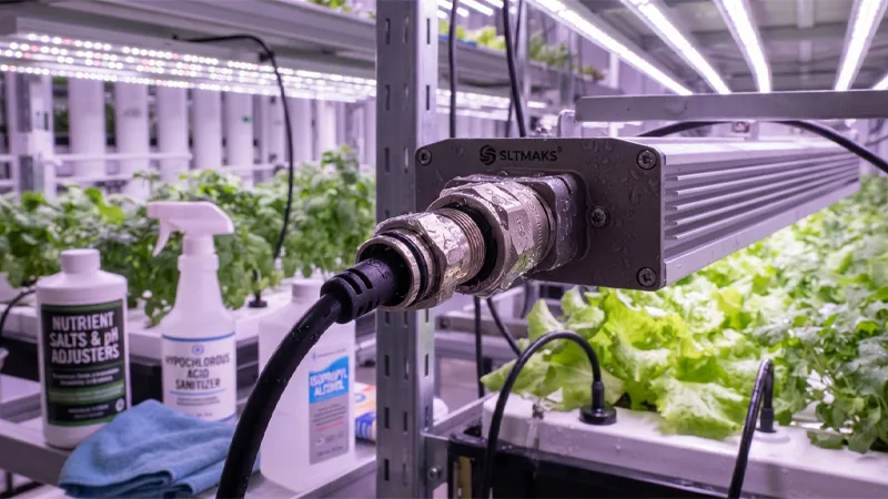
Material selection is a compatibility exercise, and it only works if the chemical list is real. Write down what the facility actually applies: nutrient salts and pH adjusters, hypochlorous acid or peroxide sanitizers, isopropyl or other solvents used for cleaning, and whatever the cleaning crew sprays that nobody documented. Then check the seal compound and the housing against that list.
The Apple Rubber seal design guide’s chemical compatibility table is a useful framework, and its limits are as important as its entries. Its ratings are stated for room temperature — the table header reads “All recommendations for 70° temperature” — and it grades Good, Fair (OK for static seal), Questionable (OK for static seal), and Poor. The “static seal” qualifier matters: a connector O-ring in a coupling that is unmated and re-mated regularly is not purely static, and a Fair or Questionable rating is not a green light for that duty.
Applying the table to the elastomers commonly found in connector seals:
- Silicone is rated Poor against steam to 350 °F and Poor against fresh water in the table’s grading, despite an excellent temperature range. It is a poor default for a wet, warm connector.
- EPDM rates well against many acids, bases, and salts — sodium hydroxide, potassium nitrate, and sodium chloride all read Good — but Poor against petroleum-based lubricating oils and mineral oils. It is a strong candidate for a nutrient-and-sanitizer environment and a poor one where hydrocarbon lubricants are used nearby.
- Fluorocarbon (FKM/Viton) combines high temperature resistance with broad chemical resistance; the guide describes fluorocarbon compounds as approaching the ideal for a universal O-ring material, with a standard compound range of −13 °F to +446 °F. It is not universally inert — the table shows Poor or Fair against some amines and ketones — but it is the usual starting point for a hot, chemically diverse fixture.
- Nitrile (Buna-N) is good against many oils and greases and Poor against many ketones and chlorinated solvents. It is common in connector seals, including as the O-ring material in one power connector family, and it is the compound most likely to be attacked by a solvent-based cleaning regimen.
- Viton O-rings and gaskets appear in the M16 connector family referenced here, alongside nickel-plated brass bodies and coupling nuts and a polyamide body moulding rated UL94 V-0.
A room-temperature table entry does not predict performance at an elevated fixture temperature or under continuous immersion. Concentration matters too: a sanitizer used at label dilution and one used at triple strength are different exposures. Verify against the seal supplier’s data for the exact compound, at the actual concentration and temperature, and run an in-situ trial before committing a facility standard.
Housing materials carry their own risks. PA66 nylon is common on M19 products, and UV-stabilized variants are available — a relevant distinction, because UL 8800 explicitly addresses UV exposure of polymeric materials, whether from sunlight in a greenhouse or from the luminaire’s own source, on the basis that such exposure can make polymers brittle and more susceptible to breakage. Nickel-plated brass bodies and coupling nuts avoid the polymer UV question on the shell but introduce a corrosion question in a humid, salt-bearing environment. Neither choice is automatically correct; both need to be matched to the room.
How to Specify Torque, Strain Relief and Bend Radius During Assembly
Most field failures at the connector are mechanical, and most of them are installation errors rather than product defects. Three parameters cover the majority: torque, gland sizing, and strain relief. A fourth — bend radius — decides whether the assembly survives being raised and lowered.
Torque. Specify the manufacturer’s coupling-nut and gland-nut torque and require a torque tool. “Hand tight” is not a specification, and the same hand produces different results on a cold morning and after a shift. Published values exist to be used: one connector family lists gland nut torques of 2.25 Nm and 0.9 Nm for different body styles, alongside cable retention forces of 150 N and 80 N depending on connector diameter. Put the value on the work instruction and audit it.
Gland sizing. The gland must match the actual jacket diameter, not the nominal cable size. Families that publish cable acceptance ranges also sell alternative glands for different cable sizes — one range offers gland packs for 5.0–7.0 mm, 7.0–13.0 mm and 13.0–15.0 mm cables, and another offers glands to suit 11–13 mm, 9–11 mm and 7–9 mm. A gland that is too large for the jacket will not seal regardless of the O-ring; one that is too small will not close over the jacket and may damage it. Measure the jacket, not the conductor insulation.
Strain relief. The cable, not the contacts, must carry the load. On a fixture that is raised and lowered, the connector hangs below a moving light bar, and every lift applies a tensile and bending load at the gland. Set the cable route so the first support is close to the connector, and check that the retention force the manufacturer declares is adequate for the load the routing imposes.
Bend radius. Industrial cable datasheets commonly state two radii: a larger one for installation and a smaller one for installed, fixed service. One PUR-jacketed cable in the reference material specifies 10 × outer diameter for installation and 6 × outer diameter installed. A connector hanging below a moving bar is a dynamic application, so design to the installation figure at any point that moves, and treat the installed figure as applying only to cable that is fixed in service. PUR jackets are generally preferred where tight bending radii and repetitive movement are involved.
O-ring handling. Four rules from seal practice: confirm gland fill is correct, since excessive fill can damage the O-ring during assembly when it swells in contact with chemicals or expands thermally; keep stretch on the O-ring I.D. to no more than about 5%, because greater stretch reduces cross-section and loses seal compression; lubricate with a compound compatible with both the seal and the system chemicals, and clean all gland surfaces of debris before installation; and make sure mating surfaces are clean and undamaged. Check the lubricant against the compatibility discussion in the previous section — a hydrocarbon grease on an EPDM seal is the wrong pairing.
What to Test at Incoming Inspection and After Installation
The test regime should be proportionate to risk and grounded in the standards already discussed. Two gates matter: goods-in, and post-installation.
- Verify the part number against the purchase specification, including contact count, termination type, and gland size.
- Verify the IP claim and its test basis: which standard, mated or unmated condition, and for IP68 the stated depth and duration. An IP68 claim without depth and duration is not a specification.
- Check contact resistance and insulation resistance against the datasheet. The M16 family referenced here publishes contact resistance below 5 mΩ for 3–8 pole and below 3 mΩ for 12 pole, and insulation resistance above 1000 MΩ — values you can compare against a sample.
- Visually inspect O-rings and contacts for damage, contamination, and correct seating.
- Run a sample mating-cycle check against the declared mechanical operation figure (500 cycles for the M16 family; 1500 insertion cycles for the M19MF product).
After installation:
- Continuity and polarity on every circuit.
- Insulation resistance on every circuit.
- A visual and torque audit of every coupling and gland nut.
- For connectors in washdown or high-condensation zones, a representative IP verification, or at minimum a documented spray test with electrical checks performed after the water exposure — not just a visual “no water inside” check. A connector that passes a visual inspection and fails an insulation-resistance check has failed.
Be clear about what an in-house spray test proves. IEC 60529 tests are type tests, pass/fail against defined conditions, carried out under specified atmospheric conditions and with defined sample mounting. An in-house spray is a screening tool for workmanship and assembly discipline; it is not a certification and does not convert a product’s rating into a different one.
Finally, set a re-inspection interval tied to the cleaning cycle. Repeated pressure washing and chemical exposure degrade seals over time, and a connector that passed at commissioning is not the same connector after two years of washdown. Tie the interval to the cleaning frequency and to any observed change in the seal’s appearance, and replace seals on schedule rather than on failure.
How UL 8800, NRTL Listing and AHJ Review Apply to the Connector and Cable Assembly
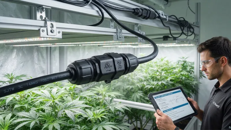
The connector sits inside a compliance chain, and it is easy to mistake one link for another.
The standard. UL 8800, the Standard for Safety for Horticultural Lighting Equipment, was introduced in 2017 and provides published safety requirements for lighting equipment and grow systems intended for horticultural use and installed in accordance with the National Electrical Code. Its scope covers luminaires and, when a horticultural system is assessed, can also include an assessment of lampholders, wire harnesses, plugs and connectors, LED packages, ballasts/LED drivers, lamps, and hardware and structures. Harmonized ANSI/CAN/UL 8800 was published in August 2019 for the US and Canada, supporting certification of lighting products and accessories such as wire harnesses.
The requirements that bear on connector selection.
- Damp location rating. Horticultural luminaires must be rated suitable for damp environments in accordance with ANSI/UL 1598 / CSA C22.2 No. 250.0 for fixed luminaires, and must comply with both the rain and sprinkler tests of Clause 13.4.8 of ANSI/UL 1598, with location designations LOC-3 through LOC-6 applying by installation type.
- Ingress protection. A luminaire exposed to dust and water can be marked with an IP code of IP54 or higher from IEC 60598-1, and that rating may appear in the “Other Ratings” section of the certification report.
- Elevated ambient. Temperature testing is conducted at the rated ambient rather than at 25 °C — a direct consequence of horticultural luminaires commonly operating in elevated ambient conditions.
- UV exposure of polymeric materials. UL 8800 sets requirements to address embrittlement of polymers exposed to UV, whether from the sun or from the luminaire itself.
- Supply connections. Luminaires are to be provided with an outlet box for fixed wiring or with a cord; cord-connected luminaires need a flexible cord of at least hard usage type, and a plug, where used, must be suitably rated for the environment, with consideration of elevated ambient temperatures, corrosion, and high humidity.
- Positioning flexibility. UL 8800 allows specialized wiring and connection methods that support the frequent raising, lowering, and repositioning of horticultural lighting systems — which is precisely the duty that makes strain relief and mating-cycle endurance connector selection criteria rather than footnotes.
The process layer. An NRTL — UL, Intertek/ETL, TÜV, and similar bodies — lists the luminaire or assembly. The AHJ (Authority Having Jurisdiction) reviews the installation against the NEC and against the listing. A field-assembled connector that is not part of a listed assembly may require field evaluation, or may not be acceptable at all, depending on the AHJ.
A connector’s own component recognition mark is not the same thing as the luminaire’s listing: recognition covers the component under its own standard, while the listing covers the assembly as evaluated. And where a project depends on utility rebates, note that DLC horticultural QPL requirements include appropriate horticultural lighting safety certification by an OSHA NRTL or an SCC-recognized body, and UL notes that certification to UL 8800 is a safety requirement to be added to, or remain on, the DLC horticultural QPL.
The practical instruction: before substituting connectors on a listed fixture, confirm with the luminaire manufacturer and the AHJ. A substitution that looks electrically equivalent may fall outside the evaluated assembly.
Cross-References and Further Reading
The sections connect in a specific order, and it is worth making the dependencies explicit before you write the specification.
IP selection depends on the cleaning regimen described in the materials section: if the crew uses a hot pressure washer, the exposure is a numeral 9 question, and the seal compound must survive the same chemicals the IP test does not model. Derating depends on the ambient conditions established in the IP and enclosure discussion: a sealed connection point raises local ambient, and the all-loaded derating curve must be read at that ambient, not at the room setpoint.
Assembly and testing depend on both: torque and gland sizing protect the seal that the materials section selected, and the post-installation electrical checks are what verify the assembly actually achieved the rating. Every choice must then survive the compliance path in the UL 8800 section, where the assembly — not the component — is what gets listed.
Primary references used in this guide:
- IEC 60529, Degrees of protection provided by enclosures (IP Code) — definitions of the second characteristic numeral, test conditions, and the standard’s statement of what the IP code does not cover.
- IEC 61076-2-106:2011, Circular connectors — Detailed specification for connectors M16 × 0.75 with screw-locking and degree of protection IP40 or IP65/67 — scope, contact counts and terminations.
- IEC 60512-5-2:2002, Test 5b: Current-temperature derating — the standardized method for current-carrying capacity at elevated ambient.
- UL 8800, Standard for Safety for Horticultural Lighting Equipment, and UL Solutions’ horticultural lighting brief; Intertek’s summary of ANSI/CAN/UL 8800 requirements; In Compliance Magazine’s treatment of horticultural lighting considerations.
- Apple Rubber, Seal Design Guide — O-ring handling rules (including the 5% stretch limit) and the chemical compatibility table, whose ratings are stated for room temperature.
- Weidmüller’s explanation of the derating curve — the temperature-budget model and the 80% reduction to the base curve.
- Representative manufacturer datasheets as examples of the fields to demand: the Bulgin M16 series (contact resistance, insulation resistance, mating cycles, gland nut torques, cable acceptance, Viton O-rings, PUR cable bend radii) and the E-Weichat / Sunshine M19 series (current and voltage ratings by pin count, wire section, cable diameter, insertion cycles, temperature range).
Refresh note, dated November 2026: standards editions, NRTL listings, and product families change. Re-verify the edition in force, the specific listing, and the current datasheet before specifying.
FAQ
What are the key differences between M16 and M19 waterproof LED connectors?
M16 is a standardized interface defined by IEC 61076-2-106, specifying fixed, free, and rewireable waterproof LED connectors with strict characteristics. In contrast, M19 is typically a commercial family designation for waterproof LED connectors that must be evaluated based on individual manufacturer datasheets and test reports.
How do you choose the right IP rating for waterproof LED connectors in cultivation rooms?
Selecting the correct IP rating for waterproof LED connectors requires analyzing the actual cleaning regimen rather than relying on marketing sheets. For instance, washdowns involving high-pressure, high-temperature jets or solvents demand specific ratings like IP69, as standard IEC 60529 fresh-water tests for waterproof LED connectors do not account for chemical or extreme pressure exposure.
Why is current derating necessary when installing waterproof LED connectors?
Catalog ratings for waterproof LED connectors are conditional values established under specific test environments. Current derating is essential because elevated ambient temperatures inside enclosures and full contact loading reduce the thermal headroom of waterproof LED connectors, preventing component damage due to excessive heat.
What compliance standards apply to waterproof LED connectors in horticultural lighting?
Horticultural lighting and components like waterproof LED connectors fall under safety standards such as UL 8800, which evaluates damp or wet location ratings (LOC-3 through LOC-6), polymeric UV exposure, and elevated ambient temperatures to ensure listed assemblies comply with the National Electrical Code.
What are the best practices for assembling and installing waterproof LED connectors?
To ensure reliability, field technicians must use a calibrated torque tool for waterproof LED connectors, match the cable jacket precisely to the gland size to prevent leaks, and ensure the cable—not the contacts—carries the mechanical load during fixture adjustments.