

Introduction
A room rarely matches the cable lengths a fixture ships with. Row pitch is set by your rack, tier heights are set by your trellis, and the fold geometry of a multi-bar fixture is set by its hinge — none of which the standard 5 ft or 10 ft jumper knows anything about. When planning these setups, engineering reliable custom daisy chain cables ensures that every physical distance and connection requirement is met without guesswork. The deliverable that closes that gap is a measured cable schedule plus a harness package: a document a supplier can build from without a site visit, and an electrician can review before anything is ordered.
This is a layout-and-specification guide, not an electrical design. Final ampacity, overcurrent protection, conductor sizing and listing decisions belong to a licensed electrician and the authority having jurisdiction (AHJ). What you control is the physical and documentary side: where each cable runs, how long it must be, what connectors it must mate with, and how it is labeled.
When deploying high-performance custom daisy chain cables, a daisy chain in the sense used here is a series of fixtures linked from a single home run — one feed point, one fixture after another, each passing power or signal through to the next. The guide treats two chains, not one. Power chains carry mains current; control chains carry a dimming or data signal. Treating them as a single system is where most custom orders go wrong, because the two have different limits, different connectors, and different failure modes.
The procurement context matters too. Wholesale foldable grow lights — multi-bar folding fixtures bought in volume for multi-tier rooms — bring geometry into the cable specification in a way that fixed-frame fixtures do not. A cable dressed neatly on a deployed fixture can be over-stressed the moment that fixture folds for service or shipping. Step 4 deals with that specifically.
Table of Contents
Before You Begin: What the Layout Package Must Contain
Before a single cable length is written down, gather the measurements and documents below. The assumed knowledge level is comfort reading a fixture datasheet and a panel schedule; anything beyond that — circuit sizing, grounding, listing — goes to the electrician.
Room and rack geometry
- Row pitch: center-to-center distance between fixture rows, measured in the as-built room.
- Tier heights: finished height of each rack tier, plus the clearance from the fixture to the tier above.
- Fixture spacing and orientation: end-to-end gaps within a row, and which way each fixture’s connector faces.
- Service and aisle clearances: the space a person and a ladder actually need, which constrains where cable can be dressed.
Electrical locations
- Driver and junction-box locations on each fixture, including which end of the fixture they sit on.
- Home-run and panel locations, with the route the cable will take.
- Controller placement and the distance from the controller to the first fixture in each control chain.
Fold geometry (folding fixtures only)
- Hinge positions and the number of folding sections.
- Bar spacing in both the deployed and folded positions.
- Fold radius, or the minimum gap the fixture leaves for cable when closed.
Documents
- Fixture datasheet, including input current or wattage, connector type, and any stated pass-through rating.
- Controller documentation, including protocol and any stated cable-length or device-count limits.
- The panel schedule, so the electrician can confirm which circuits the chains will land on.
If any of these are missing — particularly the connector type and the pass-through rating — stop and get them from the fixture supplier before specifying cable. A schedule built on assumed connector data produces an order that cannot be installed.
Step 1: Capture the Room Layout as a Measured Cable Schedule
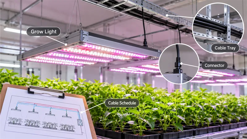
The schedule is the core deliverable. It converts a physical room into a table a supplier can read without visiting. Build it as a spreadsheet with one row per cable run, and use these columns:
| Column | What goes in it |
|---|---|
| Zone/tier ID | A short identifier, e.g. A-3 for Zone A, tier 3 |
| Run ID | Unique per chain, e.g. A-3-P1 for power chain 1 |
| Chain type | Power or control |
| Fixture count per run | Number of fixtures on that chain |
| Home run to first fixture | Measured length, in the units the supplier quotes in |
| Fixture-to-fixture spacing | Measured gap between connector entry points |
| Drop length at each fixture | Any vertical drop from cable tray or rack rail to the connector |
| Termination point | Panel, controller port, or last fixture |
| Connector type and gender | At each end, from the datasheet |
Two measurement rules do most of the work. First, measure to the connector entry point, not the fixture center. A fixture whose connector sits 200 mm in from the end of the housing will consume 200 mm of cable you did not budget for, and on a tight row that is the difference between a service loop and a straight pull on the connector. Second, record the as-built condition, not the design drawing. Racks settle, trays get moved, and a schedule that matches the drawing but not the room will produce cables that are uniformly the wrong length.
Add a column for the measured length plus a service allowance, and state the allowance explicitly so the supplier builds to it rather than guessing. Keep the allowance modest and consistent; a large allowance on every cable creates coils of slack that have to be dressed somewhere.
Verification checkpoint. Walk the room with the printed schedule. For every row, trace the run from home run to termination, confirming each fixture in the chain is the one you listed and each measured length matches what the tape says. Any row you cannot trace end to end is a row that will produce a wrong cable.
Step 2: Separate the Power Chain from the Control Chain
Power and control are separate chains with separate rules, and they should be scheduled, ordered, and installed as separate items even when they run in the same tray.
Power chains carry mains current. Their limits are set by conductor ampacity, connector rating and the branch-circuit overcurrent device. They are governed by the NEC and by the fixture’s listing, and the relevant numbers come from the fixture datasheet, the connector datasheet, and the panel schedule. Flexible cords and cables have their own ampacity tables and their own restrictions on use, and the NEC requires that tension — including the weight of the cord itself — not be transmitted to conductor terminals; strain-relief fittings are the accepted way to achieve that (EC&M).
Control chains carry a low-voltage signal. Their limits are set by protocol, topology, and total cable length. The protocol is not a preference — it is whatever the fixture’s driver and the controller both support, and the fixture datasheet and controller documentation are the authority. The four you will encounter most often behave differently:
- 0–10 V is an analog dimming signal. It is simple and widely used, and it is what many horticultural fixtures and dimming harnesses are built around; Fluence’s Dim Flex system, for example, is specified as a modular 0–10 V DC dimming wiring system with a stated maximum of 50 fixtures and 200–300 ft from first to last fixture per branch (Fluence part sheet). Those figures are that system’s limits, not a general rule.
- PWM is a pulsed signal, and its behaviour over long cable runs depends on the driver’s input design; check the driver documentation rather than extrapolating from a 0–10 V system.
- RS-485 is a differential multi-point bus. Texas Instruments’ application note on its practical limits describes it as a party-line bus where a ring created by connecting both ends will not work, star configurations are discouraged because each device sits at the end of a long stub, stubs should be kept short, and the standard allows 32 unit loads with a 4000 ft maximum cable length at 100 kbps (TI SNLA042A).
- DALI is a two-wire digital bus. Tridonic’s DALI manual states that there are no special topology requirements — star and mixed networking are permitted, but ring, fully connected and mesh networks are not — with a maximum of 64 units per line, a maximum 2 V drop along the control line, and a maximum line length of 300 m at 1.5 mm² conductor cross-section (Tridonic DALI manual). DALI wiring is polarity-independent, which removes one class of installation error, but the addressing and current limits still apply.
These are not interchangeable. A 0–10 V dimmer will not drive a DALI bus, an RS-485 chain will not tolerate the star layout a DALI line accepts, and the cable-length limits differ by an order of magnitude. Confirm the protocol from the documentation before the control chain is scheduled, because the protocol decides whether the chain is a simple series run or a bus with a termination at the far end.
One more distinction worth writing into the schedule: some systems combine mains and control conductors in a single cable. That is permitted in some installations, but the cable must be rated for the higher voltage present. Tridonic notes that line voltage and bus line may be routed in the same cable provided the cable is designed to take the maximum operating voltage. If you are not certain the combined cable is rated for mains, schedule separate cables.
Step 3: Calculate Pass-Through Load and Decide Where to Split the Chain
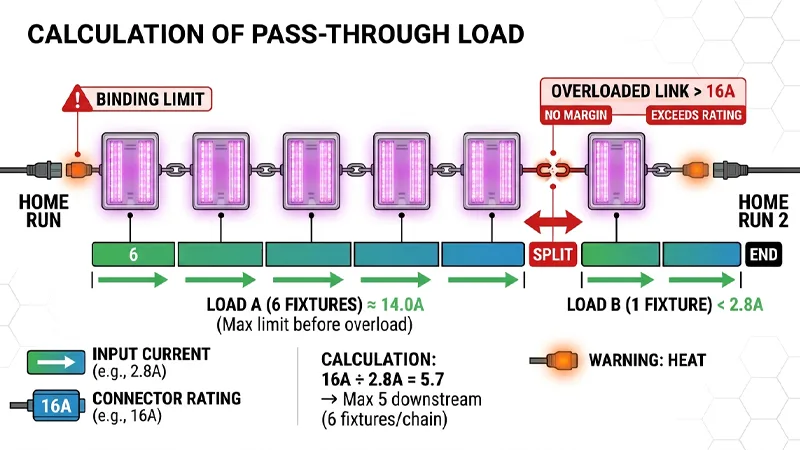
The number of fixtures that can share one chain is not a universal figure. It is the lowest of three limits: the connector’s rated pass-through current, the conductor ampacity, and the branch-circuit overcurrent protection. The calculation is a running sum along the chain.
Illustrative arithmetic only, not a manufacturer specification. Assumes six identical 650 W fixtures at 240 V (≈2.71 A each), unity power factor, no derating, and a 16 A pass-through connector rating. Each bar is the current passing through that link’s connector toward the remaining fixtures; the last link carries nothing onward. The connector rating and the branch-circuit overcurrent device — not this chart — set the real split point.
The arithmetic. Take the fixture’s input current from the datasheet — not its wattage divided by a nominal voltage, unless the datasheet gives no current figure. Then sum along the chain:
- At fixture 1, the chain carries the current of fixtures 2 through n passing through fixture 1’s connector.
- At fixture 2, it carries fixtures 3 through n.
- At the last fixture, it carries nothing onward.
The connector at the home-run end carries the full chain current; the connector at the far end carries none. That is why the pass-through rating at the first fixture is the binding constraint, and why a connector rated for the fixture’s own draw is not automatically rated for the chain’s summed draw.
The continuous-load basis. The NEC defines a continuous load as one where the maximum current is expected to continue for three hours or more, and most commercial lighting is treated as continuous (EC&M). Branch-circuit conductors must be sized at not less than 125% of the continuous load plus 100% of the noncontinuous load (EC&M). A grow room running an 18-hour photoperiod is unambiguously in that category. So the circuit sizing basis is 1.25 × the connected load, and the electrician confirms the resulting breaker and conductor size.
Voltage drop. NEC 210.19(A) Informational Note No. 4 gives 3% for a branch circuit and 5% combined feeder plus branch circuit as recommendations, not mandatory requirements. They become practically enforceable through local amendments in some jurisdictions, commercial energy code provisions, utility service requirements, and ordinary engineering practice (CalcEngineer). For a grow room, the practical consequence is that a long, heavily loaded chain can sit within connector and conductor ratings and still deliver a noticeably lower voltage at the far end. If the run is long, ask the electrician to check voltage drop before the split points are fixed.
Worked example, with assumptions stated. Suppose a fixture datasheet lists 2.8 A input at 277 V, and the fixture’s pass-through connector is rated 16 A. Ignore, for the moment, the branch circuit and look only at the connector:
- 16 A ÷ 2.8 A = 5.7, so no more than five fixtures can be downstream of any one connector on that basis alone.
- A six-fixture chain would put 5 × 2.8 A = 14.0 A through the first connector, which is within 16 A but leaves only 2 A of margin.
- A seven-fixture chain would put 6 × 2.8 A = 16.8 A through it, which exceeds the connector rating.
Now check the circuit. Seven fixtures at 2.8 A is 19.6 A connected; at 125% that is 24.5 A, which does not fit a 20 A branch circuit and points to a 30 A circuit — at which point the connector, not the breaker, is the binding limit. The split point is therefore set by the connector at five or six fixtures, and a second home run is needed for the rest of the row.
These numbers are illustrative. Substitute your own datasheet values, and have the electrician confirm the circuit sizing and the overcurrent device.
Verification checkpoint. For every chain in the schedule, write the summed pass-through current at the first fixture next to the connector’s rated current. If the margin is thin, split the chain. A chain that is technically within rating but has no margin will be the first place a marginal connector shows up as heat.
Step 4: Design Around Foldable Fixture Geometry
A fixed-frame fixture presents a cable with a simple problem: reach from A to B without a tight bend. A multi-bar folding fixture presents a second problem: the same cable must survive the fixture’s folded state, which may be the state it spends most of its life in between shipments, or the state it enters every time a technician services the row.
The hinge and fold radius set the minimum space the cable can occupy when the fixture is closed. If the cable is dressed for the deployed position — routed along the bar, clipped at intervals, entering the connector at a comfortable angle — folding the fixture can pull that same cable into a radius far tighter than its rating, right at the connector exit. The failure does not appear at installation. It appears months later as an intermittent fault or a split jacket within centimeters of the backshell.
The mechanical reason is a stiffness discontinuity. A rigid connector joined to a flexible cable concentrates deformation in whatever section is still free to move — usually the short length of cable immediately behind the connector. Cable assembly guidance describes the exit as a three-part system of rigid termination, strain-relief structure and free cable, and recommends dimensioning the distance from the exit to the first allowed bend and to the first clamp on the drawing rather than leaving it to installer judgment (Teyconn).
Three things follow for the schedule:
Bend radius at the connector exit. Get the cable’s published minimum bend radius for the installation condition — static, occasional movement, or continuous flex — and confirm which one applies. Manufacturers often publish a larger limit for moving use than for fixed installation, and the ratio varies by product, so the datasheet value governs, not a rule of thumb. Then measure the radius the fixture’s fold actually enforces. If the folded geometry is tighter than the cable’s rating, the cable specification is wrong, not the installer’s technique.
A stiffness gradient, not a sharp edge. A molded taper, a backshell with a gradual profile, or a clamp positioned so curvature builds over distance all spread the angular change across length. A bend limiter can enforce a minimum exit radius but carries no axial load by itself. Whatever hardware is used, verify the radius it actually enforces at maximum curvature; a mismatched backshell can impose a tighter effective radius than no hardware at all.
Cold and jacket stiffness. A jacket that is flexible at 20 °C may be noticeably stiffer at the low end of a room’s temperature range, and a stiffer jacket at the same bend radius means higher stress in the conductors. If the room runs cold — or the fixture is stored cold between cycles — check the cable’s temperature rating against the actual condition rather than the nominal one.
The practical output is a fold-test requirement in the harness package: state the folded geometry the cable must tolerate, and require the sample to be cycled through the fold before the full order is released.
Step 5: Assemble the Harness Drawing and Cable Schedule Package
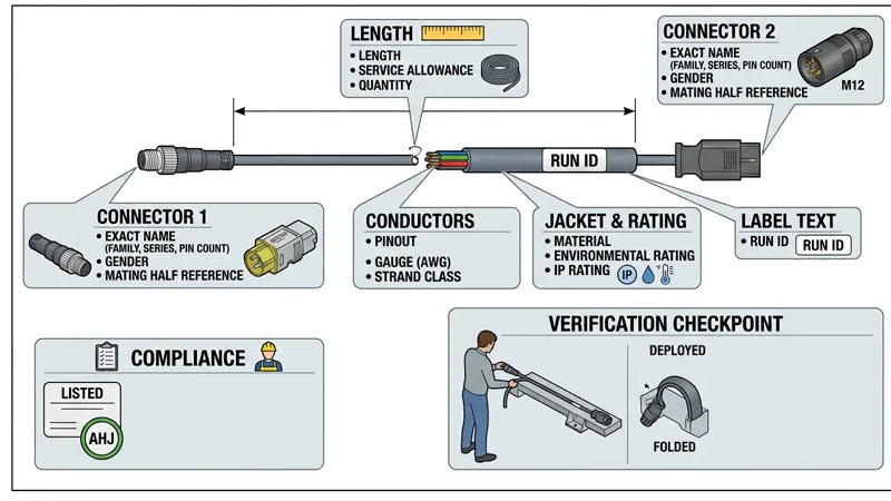
The package you send to a manufacturer or supplier should let them build without asking questions. It contains two things: a harness drawing and the cable schedule from Step 1, extended with the electrical and mechanical detail.
What each cable line needs
- Length, measured to the connector entry point, plus the stated service allowance.
- Connector type and gender at each end, named exactly — family, series, pin count, and mating half.
- Pinout, with conductor colors or numbers assigned to each pin.
- Conductor gauge and strand class.
- Jacket material and environmental rating.
- Label text, matching the schedule’s run ID.
- Quantity per length.
Why the connector must be named exactly. Connector systems are generally not cross-compatible between fixture brands. Iluminar fixtures use Wieland GST18 connectors, ThinkGrow and PHOTOBIO use their own systems, and Gavita uses Souriau or proprietary connectors depending on fixture generation; these are not interchangeable (Hydrobuilder). A drawing that says “matching connector” will produce a cable that does not mate. Name the exact part, and where the fixture supplier publishes a mating connector or a cord set, reference that part number.
The same applies to control connectors. Dimming systems use specific connector families — M12 and M16 threaded or push-lock connectors, RJ45 for some proprietary links, M8 for others — and the pin count and gender matter. A 4-pin M12 and a 3-pin M12 are different connectors. Write the pinout, not just the family.
Listing and suitability. Custom cable assemblies are not automatically listed, and the AHJ decides what is acceptable. Where a listed assembly is not available, field evaluation may be an option; EC&M notes that field evaluation bodies can examine equipment and affix a label indicating compliance with an accompanying report, and that field labeling is typically acceptable to AHJs even where the assembly is not listed (EC&M). Raise this with the electrician early, because it affects which supplier you can use.
Verification checkpoint. Before the full order is released, have one sample cable built to the drawing and fit-test it on a representative fixture — in both the deployed and folded positions. Check that the connector mates without force, that the bend at the exit is within the cable’s rating in both positions, and that the label matches the schedule. A sample that fails costs one cable; a full order that fails costs a season.
Step 6: Set Labeling and Spare-Parts Conventions for Multi-Tier Rooms
A multi-tier room has hundreds of cables that look alike. The labeling scheme is what makes the difference between a five-minute fixture swap and an hour of tracing.
Use the same identifiers as the schedule, and make the label carry the full address: zone, tier, run, and position in the run. A label reading A-3-P1-04 tells a technician that this is the fourth cable position on power chain 1 in Zone A, tier 3, without opening a drawing. Apply the label at both ends of every cable, and at any point where the cable passes through a tray or bulkhead, so it can be identified without pulling it out.
Label the fixtures to match. If the fixture at position 4 is labeled A-3-P1-04, a replacement can be ordered and installed against the schedule without re-measuring the room.
Spare parts. Keep spares in the lengths that are hardest to replace quickly — the longest runs and any cable with a non-standard connector. A workable starting point is one spare per distinct cable length per zone, plus one spare of any custom connector assembly. That is a judgment call, not a standard; adjust it to the cost of downtime in your operation and the lead time on a replacement.
Store the as-built schedule. The schedule that ships with the order is not the schedule that matters a year later. Update it whenever a cable is replaced, a fixture is moved, or a run is split, and keep the current version where the maintenance team can find it. A replacement ordered from an out-of-date schedule will be the wrong length.
Common Mistakes to Avoid
Measuring to the fixture center instead of the connector entry. The cable arrives short, and the installer compensates by pulling the connector or leaving a tight bend at the exit. Fix: measure to the connector entry point, and mark the entry point on the fixture with tape during the survey.
Mixing power and control conductors without confirming the cable rating. A combined cable is only acceptable if it is rated for the higher voltage present. Fix: if the rating is not stated, schedule separate cables.
Assuming a connector’s ampacity matches the fixture’s draw. The connector at the home-run end carries the whole chain, not one fixture. Fix: write the summed pass-through current next to the connector rating for every chain.
Ordering the full run before fit-testing a sample. A drawing error becomes a full order of unusable cables. Fix: one sample, fit-tested in both deployed and folded positions, before release.
Dressing cables only in the deployed position on a folding fixture. The cable passes inspection and fails months later at the connector exit. Fix: fold-test the sample, and specify the folded geometry in the harness package.
Treating a standard cord as a substitute for a scheduled cable. Off-the-shelf cords are fine where they fit, but mixing them with custom cables requires confirming connector compatibility across the whole run, not just at the joint.
Verifying the Finished Installation
The end-state check has four parts, and each maps to a section of the schedule.
Continuity and polarity on control chains. With the chain isolated, confirm continuity end to end on each conductor and confirm that the polarity is correct where the protocol requires it. DALI is polarity-independent, so a reversed pair is not a fault there; 0–10 V and many proprietary links are not, so check against the pinout in the drawing.
Summed load against the schedule. For each chain, confirm the fixture count and the summed pass-through current match the schedule. A chain that was split during installation but not recorded is a chain that will be mis-loaded at the next fixture replacement.
Terminations and strain relief at every connector. Check that each connector is fully seated and locked, that the cable is supported so its weight is not carried by the terminals, and that the bend at each exit is within the cable’s rating in both the deployed and folded positions.
Functional test across the full run. Drive the control chain from the controller and confirm every fixture responds — dimming range, response time, and that no fixture drops out at the low end of the range. A fixture that responds at 50% but not at 5% is a signal-integrity problem, not a fixture problem, and it usually points at the far end of the chain.
Final inspection and sign-off rest with the AHJ and the licensed electrician. Before they sign, update the as-built schedule to match what was actually installed — including any split points added on site and any cable substituted during the build.
Conclusion
The value of this process is a room that can be maintained fixture by fixture. That comes from six things: a measured schedule built from the as-built room, power and control chains separated and specified against their own rules, a pass-through load calculation that sets the split points, cable dressing designed around the fixture’s fold geometry, a harness package that names every connector and pinout, and a labeling scheme that ties every cable back to the schedule.
None of it requires an electrical design from you. It requires measurement, documentation, and a conversation with the people who do own the electrical decisions.
The next action is a review, not an order. Take the schedule and the harness drawing to the electrician and to the supplier, and ask two questions: does the circuit sizing and overcurrent protection match the chain loads, and can the supplier build to the drawing as written? Resolve both before the order is released.
FAQ
Can I use off-the-shelf daisy chain cords instead of custom daisy chain cables?
Often yes, where the row spacing, tier heights and fixture geometry fall within the standard lengths the supplier offers. Custom daisy chain cables become necessary when the measured distance to the connector entry point does not match a standard option, when tier heights require a specific drop, or when the fold geometry of a multi-bar fixture rules out the standard cable’s bend behaviour. The schedule work applies either way, and if you mix standard cords and custom daisy chain cables on one run, confirm connector compatibility across the whole run — not just at the joint between the two.
How do I know whether my custom daisy chain cables need 0–10 V, PWM, RS-485 or DALI control?
The fixture datasheet and the controller documentation decide it. The protocol is a property of the driver and the controller, not a preference, and both ends must match before you specify custom daisy chain cables. The protocol then sets the topology and length limits: RS-485 is a multi-point bus that discourages star and ring topologies and specifies termination at each end, while DALI permits star and mixed layouts but not ring, fully connected or mesh networks, with a 64-unit limit per line and a 300 m maximum at $1.5\text{ mm}^2$. No protocol is universally better; the right one is the one both ends of your system support.
How many fixtures can I connect using custom daisy chain cables?
The limit is the lowest of the connector’s rated pass-through current, the conductor ampacity, and the branch-circuit overcurrent protection, calculated on the summed pass-through load at the first fixture. There is no universal fixture count for custom daisy chain cables. The fixture datasheet and the connector datasheet supply the numbers, and the electrician confirms the circuit sizing for your custom daisy chain cables.
What should I do if custom daisy chain cables fail at the connector?
Compare the installed geometry against the custom daisy chain cables’ published minimum bend radius before reordering. The likely causes are a bend tighter than the rating at the connector exit, missing or mismatched strain relief, or a connector not rated for the environment. If the geometry is within rating and the failure recurs, check the connector’s mating condition and the environment before assuming the custom daisy chain cables specification is at fault.
Do custom daisy chain cables need a specific environmental rating?
Yes, custom daisy chain cables should match the room’s actual conditions — humidity, washdown, temperature range — and the fixture’s own rating is the starting reference. Do not assume a higher IP number covers every condition: the water-ingress ratings are not cumulative beyond IPX6, so a device rated for immersion is not necessarily rated for water jets, and standard IP testing uses fresh water rather than nutrient solutions or cleaning chemicals (IP code). Confirm the ratings for your custom daisy chain cables and connectors against their datasheets for the specific conditions in your room.