
Introduction
In a high-power LED grow light, the LED package is rarely the hottest thing in the fixture — the joint between the LED module and the heat sink often is. Two machined or cast surfaces never touch perfectly. Microscopic asperities hold them apart, and the resulting air film, with a thermal conductivity around 0.026 WmK, behaves like a blanket over the heat path.
To maintain optimal thermal management and prevent overheating, engineers rely on specialized grow light thermal materials—such as thermal interface materials (TIM)—to displace that air. Its job is not to be a conductor in isolation but to make the real joint — wetted, void-free, and mechanically stable over thousands of photoperiod cycles — as close as possible to a continuous solid.
That framing is why the paste-versus-pad question cannot be settled by comparing datasheet conductivity numbers. The right format follows from the joint how flat and parallel the mating surfaces are, how the module is clamped, whether the joint must hold off mains-referenced voltage, and how the fixture will be serviced over a multi-year life. This article works through those criteria in that order. It draws on TIM manufacturer catalogs, published reliability studies and the luminaire safety standards framework; it is not based on our own bench testing, and where the literature is silent or conditional, the text says so rather than filling the gap.
Table of Contents
Quick Comparison: Paste vs. Pad at a Glance
The table below summarizes the comparison. Property ranges are the ranges published across the catalogs cited in this article, not universal rules; a specific product may sit anywhere inside or outside them.
| Criterion | Thermal paste / grease | Thermal pad / gap filler |
|---|---|---|
| Best-fit joint | Flat, parallel, tightly clamped COB-to-heatsink interface | Bar or panel assembly with a defined gap, tolerance stack-up, or multiple heat sources |
| Typical bond line | Very thin; greases are characterized at 25–150 µm in published test work | Fixed by the pad’s compressed thickness; standard gap fillers run roughly 0.25–5 mm |
| Published conductivity range | About 0.5–7 W/mK for greases and phase-change materials | About 0.5–10 W/mK for gap fillers |
| Contact resistance behavior | Wets surfaces and drives contact resistance down at moderate pressure | Depends on compression and surface wetting; a hard pad at low pressure can leave high contact resistance |
| Electrical isolation | Not an insulation layer by default | Dielectric pads and insulator pads carry rated dielectric strength and volume resistivity |
| Rework / serviceability | Difficult; cleaning and re-dispensing required | Generally removable and replaceable; some products are rated for reuse at the designer’s judgment |
| Pump-out / dry-out risk | Real risk under power cycling and elevated temperature | Generally more stable, but documented degradation exists and loss of compression can open the interface |
| Assembly method | Dispensing, stencil printing or screen printing; clamping pressure matters | Die-cut placement, often with a pressure-sensitive adhesive or carrier |
| Best-fit use case | Minimum bond line on a flat, clamped joint | Defined gap, electrical isolation, or field serviceability |
One-line verdict: paste for thin, flat, tightly clamped joints; pads for defined gaps, isolation and serviceability. The rest of this article explains what sits behind each row.
How the Joint Geometry Sets the Decision
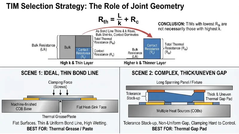
The thermal resistance of a TIM layer is usually written as the sum of a bulk term and a contact term:
R th = L / k + R c
where L is the bond-line thickness, k is the material’s thermal conductivity and R c is the contact resistance at the two interfaces. Laird’s thermal management primer uses exactly this form and draws the consequence: as the bond line thins, and as conductivity rises, the bulk term shrinks and the contact term becomes the driving force. In the limit of very high conductivity, the total resistance asymptotes to the contact resistance — no material can do better than the sum of its two contact resistances, however conductive it is. The primer states the practical implication directly: the TIMs offering the lowest thermal resistance are not necessarily those with the highest thermal conductivity.
Contact resistance is not a property of the TIM alone. It depends on the surface softness and wettability of the material and on the smoothness of the surfaces it is applied to. That is the hinge of the whole paste-versus-pad decision.
A flat, machined COB base and a flat heat-sink face, pulled together by screws, present a joint where the bond line can be made very thin and the contact term can be driven low by wetting. A bar or panel fixture, with a tolerance stack-up across a long span and several heat sources sharing one heat sink, presents a joint where the gap is not thin, not uniform, and not fully controlled by clamping. These are different problems, and the same TIM cannot be optimal for both.
Thermal Performance: Conductivity, Bond Line and Contact Resistance
Paste earns its place in thin joints because it flows. The NREL TIM study notes that greases fill the microscopic voids and cavities between mating surfaces well, producing fairly low contact resistance at even moderate pressures — below 0.2 MPa in the authors’ framing. That wetting behavior is what allows a thin, low-impedance bond line without high clamping force.
The same study measured contact resistances in the range of 6–20 mm²K/W across the commercial greases it tested, and reported that high-performance greases could reach overall resistances as low as 13 and 33 mm²K/W at bond lines of 25 and 100 µm respectively. Those are results for the specific greases and test conditions in that work, not a specification for greases generally.
Pads work differently. Their thickness is set by the product, and their impedance falls as they are compressed. Parker Chomerics publishes pressure-versus-deflection data for its gap-filler pads precisely because the in-service thermal impedance depends on how far the pad is squeezed. In its 974/976 family data, a 0.060 in (1.52 mm) sample deflects only about 7% at 5 psi and about 13% at 50 psi for the harder grades, while the softer 976 grade reaches roughly 45% deflection at 50 psi. The same catalog lists thermal impedance at 50 psi and 0.040 in (1 mm) of 0.45, 0.51 and 0.30 °C-in²/W for the three grades — differences that track softness and compression as much as nominal conductivity.
The caution follows from the equation. A pad with a high conductivity number but a hard, poorly wetting surface can post a higher joint impedance than a lower-conductivity pad that conforms better. Laird’s primer makes the point with four materials of identical 3.0 W/mK conductivity that nonetheless show four different thermal resistances, entirely because their contact resistances differ.
One measurement caveat matters for anyone comparing datasheets. ASTM D5470, the standard method behind most published TIM numbers, imposes an idealized heat-flow pattern and an average specimen temperature, and the standard itself states that the impedances so measured cannot be directly applied to most practical applications where uniform, parallel heat conduction does not exist. The standard also distinguishes viscous liquids such as greases and phase-change materials (Type I) from viscoelastic solids such as gels and soft rubbers (Type II), which is a reminder that the two formats are being characterized under one method with different mechanical assumptions. Datasheet values are a screening tool, not a prediction of your joint.
Conformability and Gap Filling: Flat COB vs. Bar and Panel Assemblies
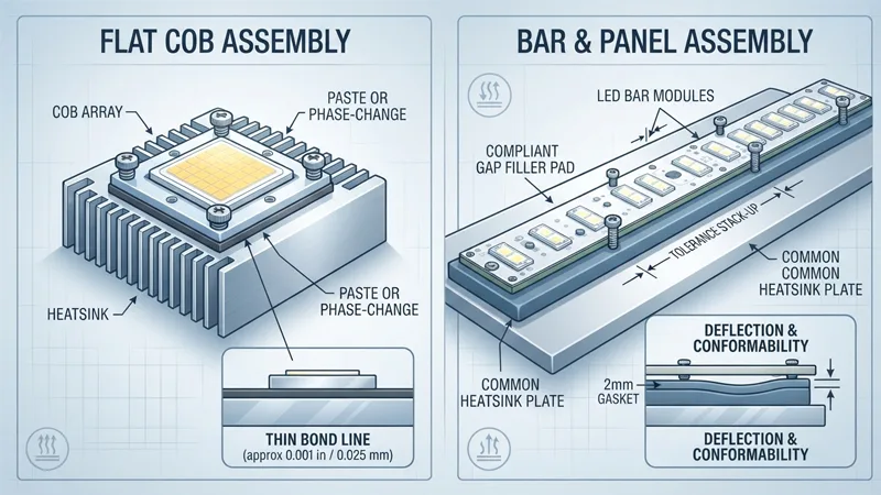
For a flat, tightly clamped COB-to-heatsink joint, paste — or a phase-change material — is the natural fit. The bond line can be made thin, the clamping pressure is concentrated over a small, parallel area, and the material’s ability to wet the surfaces does the rest. Phase-change materials add a handling advantage: Parker’s catalog describes them as solid and easy to handle at room temperature, then softening at operating temperature to conform to both mating surfaces with light clamping pressure and reach a minimum bond line below 0.001 in (0.025 mm). That is a different mechanism from grease, but it serves the same thin-joint problem.
For a bar or panel assembly, the problem changes. The gap is defined by the mechanical design rather than by clamping alone, the tolerance stack-up across the span can be significant, and one heat sink may serve multiple heat sources. Laird describes gap fillers as a class of TIMs that fill a large gap between heat-generating and heat-dissipating surfaces, often covering multiple heat sources in one application, and expected to deflect to multiple thicknesses without generating too much pressure in the system. That is the compliant-pad or gap-filler job.
Deflection behavior is where pad selection gets subtle. Laird’s white paper on resilient gap fillers reports recovery data for 2 mm gaskets across a range of conductivities. A roughly 3 W/mK material recovered about 76% of its compression; a 3.2 W/mK material recovered 43%; a 5 W/mK material recovered 7.3%; and two 7.5 W/mK materials recovered 2.6% and 0%.
The paper’s point is that highly filled, high-conductivity pads can lose resilience, and a pad that does not recover can lose contact when the gap changes — for example as the heat sink and the module expand differently under thermal cycling. The same paper notes that even the traditional high-deflection pad showed about 10% greater deflection under stress than the resilient product, yet its lack of elasticity could cause poor gap-filler contact and thermal runaway during gap change. Those figures are for the specific 2 mm samples in that study; they illustrate a mechanism rather than rank all products.
There is also a low-pressure niche where a very soft pad beats paste. If the clamping force is low enough that paste would be squeezed out of the joint rather than held in a thin film, a low-modulus pad can maintain contact where a grease film would not survive. That is a joint-design condition, not a general preference for pads.
Specifying a Pad by Compressed Thickness, Not Nominal Thickness
A pad’s nominal thickness is not the thickness that conducts heat in service. The in-service thickness is the nominal thickness minus the deflection at the actual mounting pressure, and the thermal resistance must be read at that compressed thickness. Bergquist’s Gap Pad VO Ultra Soft datasheet states the procedure plainly: use the pressure-versus-percent-deflection graph to find the deflection at the given pressure, multiply by the material thickness, subtract from the initial thickness to get the resultant thickness, then read thermal resistance at that resultant thickness. The same datasheet publishes a thickness-versus-thermal-resistance curve for exactly this purpose.
Worked as an example rather than a rule: a 0.060 in pad that deflects 13% at the intended pressure ends up at about 0.052 in, and the impedance should be read at 0.052 in, not 0.060 in. If the same pad deflects 45% because it is a softer grade, the in-service thickness is about 0.033 in and the impedance is materially different. The number that matters is the one at the compressed thickness your assembly actually produces.
Two specification details follow. First, thickness tolerance is a real variable: Bergquist lists ±5% of material thickness for Gap Pad VO Ultra Soft, while Parker’s CHO-THERM high-power insulator pads list ±0.002 in (±0.050 mm) on 0.010–0.015 in stock. A tolerance band on a thin pad is a larger fraction of the bond line than the same band on a thick one, so check it against the gap the design can tolerate.
Second, compression should stay within the material’s rated deflection range. Parker’s gap-filler catalog notes a typical deflection range of approximately 5–40% for its THERM-A-GAP pads; pushing a pad past its rated deflection risks over-stressing the module or permanently deforming the pad. The manufacturer’s pressure-deflection curve is the authority for the specific product, and the design should be checked against it at the worst-case pressure the assembly can apply.
Reliability in Service: Pump-Out, Dry-Out and Thermal Cycling
A grow light sees a hard cycling profile: daily on/off transitions for the photoperiod, high case temperatures during the light period, and repeated thermal expansion and contraction of every layer in the stack. The failure modes of paste and pads under that profile are different, and the published evidence is worth reading with its conditions attached.
Recovery rate of 2 mm gap-filler gaskets after compression, by thermal conductivity, from Laird’s resilient gap-filler white paper. Highly filled, high-conductivity pads can lose resilience, and a pad that does not recover can lose contact when the gap changes. These figures are for the specific 2 mm samples in that study and illustrate a mechanism rather than rank all products.
For paste, pump-out and dry-out are the classic concerns. NREL’s TIM report lists pump-out during repeated thermal cycling, dry-out over time and nonuniform application as the problems with greases, while noting that greases remain predominant in automotive power electronics because they fill microscopic voids well. Electronics Cooling’s reliability review explains dry-out mechanistically: grease contains no cure chemistry, so it does not cross-link, and at elevated temperature the polymer matrix can separate from the filler and flow out of the interface preferentially, leaving the grease dried out and the in-situ thermal resistance higher. The same review notes that high humidity can also change a grease layer’s resistance, depending on the filler and resin system.
The quantitative pump-out finding often cited comes from Chiu et al. (2001), as summarized in a University of Maryland dissertation: thermal grease pump-out after 2000 power cycles led to a 50% increase in interfacial thermal resistance. That is a result for the specific grease and test structure in that study, not a universal failure rate. The same dissertation cites Gektin (2005) reporting that 5% voiding in a die-to-heat-spreader TIM led to over a 70% reduction in overall system thermal performance — again, a specific configuration and a reminder of how sensitive a joint can be to voids.
More recent work sharpens the picture. A Purdue MTEC study of three commercial thermal greases under mechanical cycling found that degradation in the form of void formation increased with oscillation amplitude, and that degradation was more pronounced at lower initial squeezing pressure because the higher bond-line thickness produced a larger viscosity gradient and more voids.
At the higher squeezing pressure (0.15 MPa), one grease actually improved from beginning to end of life, likely because of better spreading; at a 200 µm bond line and lower pressure, its end-of-life resistance rose to roughly four times the beginning-of-life value through voiding and pump-out. The study’s conclusion is directly relevant to fixture design: a grease with good mechanical reliability may not have good thermal reliability, and vice versa, because performance depends on several material properties at once.
For pads, the picture is generally more stable but not failure-free. The Maryland dissertation notes that gap pads, gap fillers and putties are generally regarded as among the most reliable TIM types, yet it documents degradation: gap pad samples showed slight discoloration after 255 and 510 cycles, likely from cross-linking of the polymer matrix, and putty samples showed pump-out after 255 cycles and visible cracking at the coupon interface.
The dissertation also notes that temperature cycling can be problematic for elastomeric pads when there is a large mismatch in coefficients of thermal expansion between the mating surfaces, which can lead to loss of contact. And it makes a point that cuts against a simple narrative: for many silicone-based TIMs, thermal performance may actually improve over the course of environmental exposure as the material wets the surfaces better. The honest summary is that pads are more forgiving but not immune, and that loss of compression force or resilience is the mechanism to watch.
Electrical Isolation and Safety Compliance
Grease is not an isolation layer by default. It is a filled polymer designed to conduct heat, and nothing in a typical grease datasheet establishes a rated dielectric withstand for the joint. Where the joint must hold off voltage, the isolation has to come from a material specified for it — a dielectric pad or insulator pad with published dielectric strength and volume resistivity.
Parker’s catalog illustrates what that class of product looks like. Its CHO-THERM insulator pads are described as a user-friendly alternative to greased mica insulators between discrete power devices and heat sinks, with a silicone binder for high-temperature stability and electrical insulation, glass-mesh reinforcement for cut-through resistance, and UL-recognized flammability ratings. The high-power grades list voltage breakdown of 2,500–4,000 Vac dry and volume resistivity of 10¹⁶ ohm-cm, with thermal impedance around 0.19–0.23 °C-in²/W at 300 psi. The catalog is explicit that high mounting pressure is required to minimize contact resistance for this class — an isolation pad is not a free lunch thermally.
The safety logic that forces this choice is visible in LED module documentation. Tridonic’s design-in guide for its DLE G4 ADV module states that the module is basic-isolated against ground up to 60 V and can be mounted directly on earthed metal parts of the luminaire, but that if the maximum output voltage of the LED driver (also against earth) is above 60 V, additional isolation between the LED module and the heat sink is required — for example by isolated thermal pads — or by a suitable luminaire construction.
Xicato’s IEC 62031 test report for its XIM module carries the same logic from the module side: the module must be isolated from the metal housing of a luminaire and protected against touching when powered by a non-isolated or basic-isolated driver, and can only be used non-protected if powered by a SELV driver.
The standards framework around this is the LED equipment safety family: UL 8750 in the United States, IEC 62031 internationally, and CSA C22.2 No. 250.13 in Canada. UL 8750 covers LED modules, drivers and equipment and is used in combination with luminaire standards such as UL 1598; any OSHA-recognized NRTL, not only UL, can certify to it.
The important point for a TIM specification is jurisdictional: the authority having jurisdiction (AHJ) and the NRTL evaluate the finished luminaire, not the pad. A pad’s datasheet dielectric strength and volume resistivity are inputs to that evaluation, not a certification of the fixture. Treat the pad as one accepted method of achieving isolation, confirm the required insulation level with the luminaire safety evaluation, and do not assume a grease layer provides any of it.
Incoming Inspection and Verifying the Production Interface
ASTM D5470 is the primary steady-state method for TIM thermal impedance, and Laird describes it as the primary quality-control technique in its own testing labs. But the standard’s own scope limits what it can tell you about a production joint: it imposes idealized parallel heat flow and an average specimen temperature, and states that the measured impedances cannot be directly applied to most practical applications. It is a material-characterization and lot-consistency tool, not a substitute for measuring the interface in the fixture.
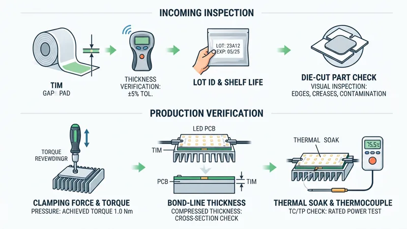
With that in mind, a practical incoming and production verification routine looks like this.
Incoming material checks
- Verify thickness against the supplier’s tolerance for the specific product — for example ±5% of nominal on a soft gap pad, or ±0.002 in on a thin insulator pad — using a method that does not pre-compress the sample.
- Control lot identity and shelf life. Parker lists shelf lives of 12–24 months from shipment depending on product family, and indefinite for dry insulator pads (18 months with adhesive); Henkel’s gap-filler guidance recommends first-in-first-out inventory and does not advocate use beyond shelf life. Record the date code on receipt.
- Inspect die-cut parts visually and dimensionally: edge quality, carrier or reinforcement integrity, liner condition, and freedom from creases or contamination.
Production interface checks
- Confirm the clamping force or fastener torque actually achieved, since both paste and pad performance depend on pressure. For paste, the Purdue work shows that lower initial squeezing pressure produces a thicker bond line and more voiding; for pads, the pressure-deflection curve is meaningless if the specified pressure is not reached.
- Check bond-line or compressed thickness on first articles. For paste, a squeeze-out witness or a cross-section on a sacrificial unit; for pads, a compressed-thickness measurement against the calculated in-service value.
- Run a thermal soak or thermocouple check on first articles at rated power, measuring case or board temperature at the specified point and comparing against the design expectation. Tridonic’s module guide, for instance, specifies measuring at the marked tc/tp point with a thermocouple under worst-case ambient and installation conditions.
These are ordinary engineering practices, not pass/fail thresholds. The acceptance limits should come from your own design analysis and the supplier’s data, not from a generic number.
Total Cost of Ownership: Labor, Rework, Downtime and HVAC
Total cost of ownership for a TIM decision turns on four things: material and dispensing cost, labor and rework, downtime over the service life, and the HVAC load the fixture imposes on the space. The comparison below is reasoning with stated assumptions, not a cost model with invented figures.
Paste. The material is usually inexpensive per part, but the process is not. Dispensing equipment, stencil or screen printing, controlled dispense volume, and a settling or cure step all add capital and labor. Rework is difficult: the joint must be opened, cleaned and re-dispensed, and the module and heat sink may not survive repeated cycles. Over life, the pump-out and dry-out mechanisms described earlier can raise junction temperature, and the Purdue and Chiu findings show that the increase can be substantial under adverse conditions. The upside is thermal: in a flat, clamped joint, paste can achieve the thinnest bond line and the lowest impedance.
Pads. Material cost per part is generally higher, and die-cut tooling adds a setup cost. But placement is simple, rework is comparatively easy, and some products are designed for reuse at the designer’s judgment — Henkel notes that some customers reuse Gap Pad material after burn-in and field repairs, while leaving the decision to the design engineer. Isolation can be built into the pad, which may remove a separate insulator and its assembly step. The downside is thermal headroom: a pad’s fixed thickness and contact resistance may cost a few degrees at the junction compared with a well-executed paste joint.
Why a small impedance difference compounds. A hotter joint raises junction temperature, and junction temperature affects both light output and lifetime. Henkel’s SIL PAD guide states that a 10 °C rise in junction temperature can reduce mean time to failure by a factor of two — a rule of thumb from that document, but a useful order-of-magnitude for the direction of the effect.
Over a multi-year service life, a joint that runs a few degrees hotter can translate into lower maintained output and earlier replacement. The same heat is rejected into the conditioned space, so a hotter fixture also adds to the HVAC load the facility must remove. In a dense vertical farm or a sealed room, that load is a recurring operating cost, not a one-time one.
The value judgment, stated plainly: if the joint is flat and tightly clamped and the fixture is not field-serviceable, paste’s thermal advantage is likely worth its process cost. If the joint has a defined gap, needs isolation, or will be serviced in the field, a pad’s lower process risk and easier rework usually outweigh a small thermal penalty. The crossover depends on your labor rates, your service model and the cost of a failed fixture — inputs only you have.
Matching TIM Format to Assembly Type
Pulling the criteria together produces three conditional recommendations.
COB modules — thin, flat, clamped. Use paste or a phase-change material where the joint is flat, parallel and tightly clamped, and where the design does not require the TIM to provide electrical isolation. If the driver configuration requires isolation between the module and an earthed heat sink, an isolating pad becomes part of the stack, and the thermal penalty of that pad has to be designed in rather than discovered later. A hybrid — an isolating pad plus a thin paste layer on the component side — is a legitimate option where both isolation and minimum contact resistance matter, but it adds an assembly step and a second interface to control.
Bar and panel fixtures — defined gap, tolerance stack-up. Use a compliant pad or gap filler sized by compressed thickness, not nominal thickness. Confirm the pressure-deflection curve at the actual mounting pressure, check that compression stays within the rated deflection range, and consider resilience if the gap will change under thermal cycling. Where one heat sink serves multiple heat sources, a gap filler that covers them in one piece can simplify assembly, as Laird notes.
Driver power electronics — isolation and mechanical robustness. Use an insulated pad or gap filler where the driver’s output requires isolation from earthed metal and where the joint must survive vibration and thermal cycling. The CHO-THERM class of insulator pads, with rated dielectric strength and glass-mesh reinforcement, is designed for exactly this role, at the cost of the higher mounting pressure the catalog says is needed to minimize contact resistance.
Each recommendation is conditional on the criteria established earlier: joint geometry, clamping, isolation and service life. Change one of those and the recommendation can change with it.
Who Should Choose Which
Three reader profiles follow from the analysis.
The fixture designer working with tight-tolerance COB mounting. Your joint is flat, parallel and clamped, so paste or phase-change material is the default for thermal performance. Your work is in the process: dispense volume control, clamping force verification, and a rework plan for the units that fail test. If the safety evaluation requires isolation, design the isolating pad into the thermal stack from the start and budget its impedance.
The operator or integrator servicing bar and panel fixtures in the field. Your joint has a defined gap and will be opened for service, so a pad is the practical choice. Specify it by compressed thickness, keep spare die-cut parts in controlled inventory with shelf-life tracking, and verify clamping force on reassembly. If the fixture was originally built with paste, a retrofit to pad is possible but changes the thermal stack — see the FAQ below.
The procurement team balancing isolation compliance and rework cost. Your decision is a TCO comparison, not a conductivity comparison. Get the pad’s dielectric ratings and the luminaire’s required insulation level in front of the safety evaluation early, confirm the NRTL’s acceptance path, and weigh the pad’s material cost against the labor, rework and downtime cost of paste. The cheaper material per part is not always the cheaper joint over life.
Edge cases. A hybrid approach — an isolating pad plus a thin paste layer on the component side — is warranted when both isolation and minimum contact resistance matter and the assembly can tolerate the extra step. Where neither paste nor a standard pad fits — for example a joint with high topography, fragile components and a large gap — a dispensable thermal gel or a phase-change material should be evaluated. Parker’s gel datasheets describe fully cured, dispensable materials that are highly conformable at low pressure and reworkable, with minimum bond lines down to 0.002–0.004 in (0.05–0.10 mm) for the high-performance grades. That is a different format with its own trade-offs, not a universal upgrade.
Frequently Asked Questions
Can thermal paste and thermal pads be used together in grow light thermal materials?
Yes, in a layered stack — typically an isolating thermal pad against the earthed heat sink and a thin thermal paste layer on the component side. When evaluating grow light thermal materials, this hybrid trade-off adds an extra interface and assembly step. Its thermal benefit depends on whether the thermal paste layer actually achieves a thin, void-free bond line. It is a specialized design option, not a default.
Can a grow light fixture be retrofitted from thermal paste to a thermal pad?
Mechanically, often yes, but the thermal stack changes. A thermal pad’s fixed thickness may be larger than the thermal paste bond line it replaces, and its contact resistance depends on the clamping pressure the existing hardware can apply. When switching grow light thermal materials, the retrofit should be checked against the thermal pad’s pressure-deflection curve and verified with a first-article thermal measurement, rather than assumed to be equivalent.
Which grow light thermal materials last longer: thermal paste or thermal pads?
There is no universal answer. Among grow light thermal materials, thermal pads are generally regarded as more stable, though documented degradation exists and loss of compression or resilience can open the interface. Thermal paste is susceptible to pump-out and dry-out, with published findings showing substantial resistance increases under adverse cycling conditions. The right question is which failure mode your joint can tolerate and how it will be detected in service.
Does higher thermal conductivity always mean a cooler LED?
No. Total joint impedance is bulk resistance plus contact resistance, and as the bond line thins or conductivity rises, contact resistance becomes the limiting term. When selecting grow light thermal materials, a high-conductivity material that does not wet or conform well can post a higher joint impedance than a lower-conductivity material that does. Laird’s primer states it directly: the TIMs offering the lowest thermal resistance are not necessarily those with the highest thermal conductivity.
Is thermal paste still relevant as grow light fixtures move to higher power?
Yes, where the joint is flat and tightly clamped and the design can control dispense volume and clamping force. Higher power raises the stakes on bond-line control, which is exactly where thermal paste’s thin-film advantage matters — and exactly where its process discipline is required. Where the joint cannot be made flat and tightly clamped, a compliant thermal pad or gap filler remains the practical choice among grow light thermal materials regardless of power level.
Verdict: A Criteria-Based Recommendation
| Criterion | Format that fits |
|---|---|
| Flat, parallel, tightly clamped joint | Paste or phase-change material |
| Defined gap or tolerance stack-up | Compliant pad or gap filler, sized by compressed thickness |
| Electrical isolation required | Dielectric or insulator pad with rated dielectric strength |
| Field serviceability required | Pad, generally removable and replaceable |
| Minimum bond line is the priority | Paste or phase-change material |
| Gap changes under thermal cycling | Resilient pad, checked for recovery |
The overall decision rule: choose paste for flat, tightly clamped, non-isolated joints where minimum bond line matters; choose pads where a defined gap, electrical isolation or field serviceability governs. In every case, specify by joint impedance at the in-service bond line and pressure, not by datasheet conductivity alone, and verify the finished interface on first articles.
If you are working through a fixture thermal design and want a second set of eyes on how the TIM choice interacts with the heat-sink and module stack, SLTMAKS’s engineering team supports OEM and ODM projects from spectrum customization through production, and can discuss the thermal constraints of a specific assembly. Share your joint geometry, clamping method and isolation requirement in the comments, and we will work through the criteria with you.