Introduction
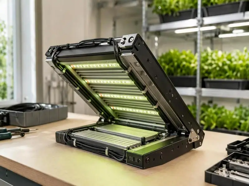
A viable foldable LED grow light design is fundamentally different from a fixed luminaire with an added hinge bolted on. The enclosure, internal wiring, and dynamic load paths all intersect at a moving joint—meaning every mechanical adjustment impacts electrical safety and regulatory compliance simultaneously. A hinge chosen merely for packaging convenience often turns into the fixture’s primary structural weak point; a cable routed across the fold without an engineered flex zone can rapidly fatigue at the termination; and a gasket that passes an ingress test in a flat position may fail when angled.
This guide is written for fixture designers, OEM engineers, and procurement or facility specifiers evaluating a foldable design. It sets out evaluation criteria for hinges, cable routing, ingress protection, structural acceptance, and certification scope, and ties each one to the documentation that can actually substantiate it. The evidence basis is component datasheets, the IEC 60529 test definitions behind an IP rating, UL 8800 scope material, and published cable-flex guidance. Where a criterion depends on the specific fixture — panel mass, fold frequency, mounting geometry — this guide names what to confirm rather than supplying a number that would not survive contact with a different design.
Table of Contents
Key Challenges in Foldable LED Grow Light Design vs. Fixed Fixtures
A foldable horticultural luminaire is a fixture whose light-emitting sections articulate relative to one another for transport, installation, or canopy-height adjustment. That single design choice breaks two assumptions that fixed luminaire standards are built around: the enclosure is no longer a single rigid body, and the wiring is no longer a static run.
Three consequences organize the rest of this guide.
The hinge becomes a structural element. It carries panel weight, and it carries it repeatedly. In a fixed fixture, a bracket sees a largely constant load. In a foldable one, the hinge sees that load through every fold and unfold, plus any handling and transport loads. Hinge selection is therefore a load-case problem, not a hardware-catalog problem.
Every conductor crossing the joint sees flex. A fixed installation assumes the cable stays where it was installed. A cable crossing a hinge bends — and possibly twists — each time the fixture moves. That is a different duty class, and it requires different cable construction, routing, and strain relief.
Ingress protection must hold at a seam that opens and closes. Every other part of the enclosure can be sealed once at the factory. The hinge line and the cable entries near it are the places where the seal is asked to work while the geometry changes.
The duty cycle implied by the use case drives how hard each of these three problems is. Folding for shipping and initial installation is a low-cycle event: the fixture might fold a handful of times in its life. Folding for routine repositioning is a different matter. UL 8800 scope material notes that horticultural lighting systems are “typically designed to be frequently raised, lowered or repositioned” to optimize plant growth, and that the standard accordingly allows specialized wiring and connection methods that support positioning flexibility. A fixture that is folded or re-angled as the canopy rises sits much closer to that description than one that is folded once in a crate.
Establish which case you are designing for before selecting hardware. A hinge and cable package that is adequate for a shipping fold can be badly under-specified for a fixture that is re-positioned weekly. The three failure modes that follow from this — hinge wear, conductor fatigue, and seal degradation — map onto the hinge, cable routing, and ingress protection sections below, and the structural and certification sections address how to prove the assembled result.
Hinge Selection: Separating a Hinge That Lasts From One That Does Not
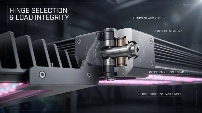
Hinge life is a function of load per hinge, cycle count, material, and bearing design. A supplier’s cycle rating is only meaningful when the test load, the angle swept, and the definition of a cycle are all stated. A number without those conditions is a marketing figure, not an engineering one.
Start with what the datasheet should tell you:
- Rated load, and whether it is static or dynamic. These are different quantities. A static rating describes holding a load; a dynamic rating describes moving it repeatedly.
- Cycle life and the test conditions behind it. Look for the load applied during cycling, the angle swept, the cycle rate, and whether the test ran to failure or to a defined inspection point.
- Load direction. A hinge may be rated for axial load, radial load, or moment. These are not interchangeable, and a rating in the wrong category tells you nothing about your application.
- Material and finish. The base metal and the coating system determine corrosion behavior in a warm, humid grow room.
- Bearing type. Plain bearing, bushing, or rolling element — each has a different wear profile and a different sensitivity to contamination.
- Corrosion resistance. Ask what the finish is rated against, not merely that a finish exists.
Then inspect the physical sample. Check bearing play by hand at the deployed position and look for slop that would let the panel droop. Confirm pin retention — a pin that can walk out under vibration is a failure waiting for a service call. Look for washers and bushings at the knuckle; their absence concentrates wear. Run a finger along any edge near the cable path: a sharp edge at the knuckle will abrade a jacket over enough cycles even if the routing looks correct. Check coating coverage at the knuckle itself, which is often the hardest geometry to coat evenly and the first place to corrode.
Finally, ask the supplier to document the test setup. The question that matters is whether the cycle rating was measured under the fixture’s actual panel weight and moment arm, and whether the rating accounts for the fixture’s environment. A hinge tested dry at room temperature in a laboratory rig is not the same component as one installed in a wet, warm, fertilizer-salt-laden grow room.
On materials generally, procurement experience from adjacent hardware categories is instructive without being directly transferable. Building-industry guidance on door hardware warns that buyers should be alert when a contractor or supplier offers a purportedly similar unit with lower-grade metals and finishes, and recommends specifying corrosion-resistant fasteners and hinges rather than carbon steel where corrosion is a concern. The lesson for grow-light hinges is the substitution risk, not the door-specific requirements: a hinge that looks identical in a photo may differ in alloy, plating thickness or bearing material.
A cycle rating also does not by itself establish suitability for a humid, warm environment. Cycle life and corrosion resistance are separate properties, tested separately, and a fixture needs both.
Reading a Hinge Datasheet Against the Actual Load Case
The comparison between a datasheet rating and your application is a moment calculation, and it has to be done in the right units and the right category.
Take the mass of the articulating panel and the perpendicular distance from the hinge axis to the panel’s center of mass. The static moment at the hinge is the panel weight multiplied by that offset distance. If a panel’s center of mass sits well out from the pivot, the moment at the knuckle is correspondingly larger than the bare weight would suggest — which is why comparing a panel’s weight in kilograms directly to a hinge’s rated load is the most common error in this selection.
Compare that computed moment to the hinge’s rated capacity in the same category — moment to moment, not moment to axial load — and apply a margin chosen by the designer for the application’s uncertainty, wear allowance, and consequence of failure. The margin is a design decision, not a standard number; state it in the design record so it can be reviewed.
Two cautions. First, a static moment comparison does not capture dynamic wear: cycling adds bearing wear, pin fretting, and finish loss that a static rating does not describe, so a hinge that passes the static check still needs a cycle rating appropriate to the fold count. Second, the comparison is only valid when the datasheet’s load definition matches the quantity being computed. If the datasheet rates axial load and you have computed a moment, you have not made a comparison at all.
Cable Routing Across a Hinge: Strain Relief and Flex Life
A conductor crossing a hinge is a dynamic-flex application, and it must be designed as one. Cable-flex guidance commonly separates duty classes along a spectrum: field installation, limp cable, casual flex, and continuous high-flex. A foldable fixture’s hinge cable sits somewhere on that spectrum depending on how often the fixture folds — near the casual-flex end for a shipping fold, closer to continuous flex for a fixture repositioned regularly. Place your design on that spectrum deliberately before specifying cable.
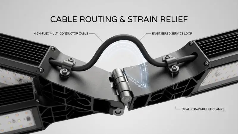
The design elements that follow from that placement:
A service loop or bend allowance sized to the cable’s own minimum bend radius. The loop must be long enough that the tightest bend the cable experiences during the full fold sweep stays above the manufacturer’s stated minimum. The coefficient comes from the cable’s datasheet, not from memory.
Strain relief on both sides of the joint. The goal is to make the flexing section a controlled length of jacket rather than a termination. If the cable is anchored at one end and free at the other, the bend concentrates at the anchor and the conductor strands work against the terminal. Anchoring both sides defines where the flex happens and keeps it away from connectors.
Routing that keeps the bend in one plane where possible. Bending flex — the back-and-forth “tick-tock” motion off a stationary point — concentrates stress at the two focal points where the bend and load are applied. Torsional flex, where the cable is twisted off its centerline, is a harsher duty. If the hinge geometry forces the cable to both bend and twist, that should be recognized in the cable specification rather than discovered in the field.
Separation from pinch points and sharp edges. OSHA’s electrical wiring requirements for construction state that flexible cords and cables shall be protected from damage, that sharp corners and projections shall be avoided, and that cords may pass through pinch points only if protection is provided to avoid damage. That principle applies directly to a hinge: the knuckle is a pinch point by construction.
When specifying cable for a high-cycle hinge, look for the construction features that continuous-flex cables are built around: a strain-relieving center element to keep conductors from migrating into the core, optimized conductor stranding, insulation that resists adhering to itself, a cabled core with controlled pitch, a pressure-extruded inner jacket rather than a fleece wrap, an optimized braid where shielding is present, and an abrasion-resistant pressure-extruded outer jacket. These are the properties to ask about; a standard building wire or hook-up wire is not designed for this duty.
Inspection tells you whether the design is working. A correctly strain-relieved run at the hinge shows an intact jacket, a smooth bend with no sharp kink, no tension at the connector, and no abrasion witness marks where the cable passes hardware. A failing run shows jacket whitening at the bend, a conductor that has taken a set (the cable stays bent when the fixture is opened), and insulation creep at the termination where the conductor has been pulled through its insulation.
Minimum Bend Radius: Getting the Coefficient From the Right Source
Minimum bend radius is specified either directly in millimetres or as a multiple of the cable’s outer diameter, for example 6 × D. It is a limit below which the cable must not be bent, not a target to hit exactly.
The multiplier varies widely by cable type and by service condition. Published guidance illustrates the spread: LAPP notes that certain of its cables may have a minimum radius of 6 times their diameter for fixed installation but 15 or 20 times their diameter for occasional movement, while cables designed for continuous operation in cable carriers may carry different requirements. A general rule of thumb sometimes quoted for continuous-motion applications is 10–12 times outer diameter, against 6–8 times for fixed installation — useful as a sanity check, but not a substitute for the datasheet of the specific part.
The common error is assuming a coefficient from memory. The coefficient should never be assumed; values vary considerably between cable types, and the presence of shielding, the conductor stranding, and the jacket compound all affect the figure. Go to the manufacturer’s datasheet for the exact part number, and confirm which motion class the stated radius applies to.
Two further points of confusion are worth heading off. Radius is not diameter: if the minimum radius is 60 mm, the corresponding bend diameter is 120 mm, and a routing drawing that dimensions a diameter against a radius limit will be wrong by a factor of two. And if the cable runs inside any kind of carrier or guide, the carrier’s bend radius must also be checked against the cable requirement — the fact that a cable physically fits inside a carrier does not mean it can operate there safely.
Ingress Protection at Hinges and Cable Entries
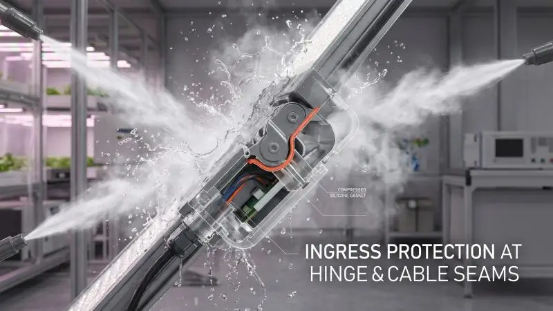
An IP rating is a defined test result, and understanding its structure tells you exactly what it certifies and what it does not. Under IEC 60529, the code has two characteristic numerals. The first covers protection against solid foreign objects and access to hazardous parts; the second covers protection against water ingress with harmful effects.
Each water numeral corresponds to a defined test with specified flow rates, durations, and orientations. Drawing on the IEC 60529 test definitions:
- IPX1 — vertical dripping, tested with the enclosure on a turntable.
- IPX2 — dripping with the enclosure tilted 15°, tested in four fixed positions.
- IPX3 and IPX4 — spraying and splashing, tested with an oscillating tube or spray nozzle; IPX4 extends the spray to ±180°.
- IPX5 and IPX6 — water jets and powerful water jets, tested with 6.3 mm and 12.5 mm nozzles respectively at defined flow rates.
- IPX7 and IPX8 — temporary and continuous immersion, with IPX8 conditions set by agreement between the parties.
Two structural points matter for a foldable fixture. First, the tests are not simply ordered by severity: IEC 60529 treats immersion and water jets as different types of ingress test, so an IPX7 rating does not automatically establish IPX6 resistance. Second, the rating is established on a test specimen in a specified configuration. That is the hinge problem in one sentence.
So the questions to put to a supplier are specific:
- Was the hinge tested in the folded or the unfolded position — or both?
- Was the cable entry tested with the cable actually installed, and at what bend?
- Is the seal at the hinge a continuous gasket under compression, or a labyrinth path?
- Does the installation marking restrict the fixture to particular positions, and does the IP claim correspond to those positions?
UL 8800 addresses ingress protection as part of its horticultural evaluation, classifying and rating the degree of protection against both solid objects and water. That means the fixture’s listing and its IP claim should be read together rather than as independent marketing statements.
This guide does not assert that a particular IP level is required for a foldable grow light. The requirement depends on the installation environment and on what the authority having jurisdiction (AHJ) accepts. What the reader can do is require that the claimed level be tied to a test report naming the configuration tested.
What the IP Test Does Not Tell You
The test is a pass/fail against a defined condition applied to a specimen in a defined state. It does not model several things a grow room will do to the fixture.
It does not model condensation from thermal cycling inside a warm, humid room. IEC 60529 itself distinguishes between enclosures whose normal working cycle reduces internal pressure below ambient — for example through thermal cycling — and those where no pressure difference exists, and applies a different dust test to the first category precisely because the “breathing” effect draws contaminants in. A wet grow room with lights cycling on and off is the first category in spirit, whatever the label says.
It does not evaluate a degraded gasket. A gasket that takes a compression set after thousands of fold cycles, or a cable jacket that abrades at the entry, can degrade protection without any change to the rating on the label. Seal materials and groove geometry are design choices — silicone, EPDM, and neoprene have different compression-set and chemical-resistance behavior — and the design should state which was chosen and why.
And it does not cover a cable entry that is only sealed when the fixture is in one position. If the entry relies on the cable approaching at a particular angle, folding the fixture can open a path the test never exercised.
These are design and verification questions to raise separately, and they are the reason periodic inspection of the seal and entry belongs in the maintenance plan rather than being assumed away by the label.
Structural Integrity: Flatness, Sag, Vibration and Drop
A foldable fixture’s structure has two jobs. When deployed, it must hold the panels in a stable plane: flatness and sag affect both light distribution across the canopy and the load seen by the hinges. During handling and transport, it must survive vibration, drop, and repeated folding. Both jobs can be written as acceptance criteria, provided each criterion is framed as a test method with a pass/fail definition rather than a universal number.
Flatness. Measured across the deployed panels, with a stated reference (a straightedge, a laser plane, or a defined datum on the fixture) and a stated tolerance. Without the reference and the tolerance, “flat” is not a specification.
Sag or deflection. Measured at a defined point under the panel’s own weight and any specified added load, with the fixture in its deployed configuration. The measurement location matters: deflection at the outer edge of a cantilevered panel is a different quantity from deflection at mid-span.
Vibration. Tested to a named method with the fixture in its transport configuration. ANSI C136.31, the American National Standard for roadway and area lighting equipment luminaire vibration, provides a vibration test method and minimum withstand capability for roadway and area luminaires. Its scope is not horticultural fixtures, so it should be referenced as a method — the reader should state the method and the acceptance level explicitly rather than assuming the standard’s default applies.
Drop and handling. With a defined drop height, orientation, and post-test functional check. A drop test that does not state which face or corner strikes first, and what must still work afterward, cannot be repeated or enforced.
Each criterion needs a measurement location, a condition, and a pass/fail threshold, or it cannot be enforced. A criterion that says “the fixture shall not sag excessively” will be resolved in the supplier’s favor every time.
Writing the Criteria Into a Purchase Order
The translation from design intent to contract language is mostly a matter of naming five things for each criterion: the test method, the configuration tested, the sample size, the acceptance threshold, and the documentation to be delivered.
Configuration is the one most often omitted and most often decisive. A flatness criterion without a stated configuration — folded or deployed — is ambiguous, and ambiguity in a purchase order tends to be resolved in the supplier’s favor. The same applies to vibration (transport configuration) and to any load case (deployed, with or without the specified added load).
Sample size matters because these are destructive or at least wearing tests. A single sample passing a drop test establishes that one unit survived one drop. State how many units, from which production stage, and whether the test is a design qualification or a production audit.
The report should be a named deliverable, not an afterthought. If the purchase order does not require the report, the test may have happened and still be unverifiable at the point of dispute.
Folding Geometry, Hinge Placement and Light Uniformity
Hinge placement determines the angle between panels when deployed and the gap at the fold. Both affect how light from adjacent panels overlaps on the canopy, and the overlap is what the plants actually experience.
A fold line that leaves a gap between emitting surfaces creates a shadow band in the distribution. A fold line that brings two panels too close, or angles them toward each other, creates an overlap band where intensity is higher than the surrounding area. Either shows up as non-uniformity in the photosynthetic photon flux density (PPFD) distribution across the canopy.
PPFD uniformity is the metric to evaluate, and like any metric, it has measurement conditions. Uniformity is measured across a defined area at a defined distance from the fixture, so a uniformity claim must state its measurement plane — the distance, the area covered, and the grid or resolution used. A uniformity figure quoted without those conditions cannot be compared to another figure, and should not be compared to a design target.
The design questions follow directly:
- Does the deployed geometry produce a continuous emitting plane, or a stepped one? A stepped plane can still be acceptable, but its uniformity must be measured rather than assumed.
- Does the hinge hardware or the cable routing cast a shadow into the canopy? A knuckle that protrudes below the emitting surface, or a cable loop that hangs into the light path, is a shadow source that a bare-panel measurement will not reveal.
- Has uniformity been measured with the fixture in its deployed configuration, rather than inferred from the output of a single unfolded panel? The deployed fixture is the product the grower installs.
The substance here is the metric and its measurement conditions. This guide does not supply a uniformity value, because the appropriate value depends on the crop, the trellis or canopy geometry, and the target the grower has set — and because a uniformity figure is only meaningful alongside the measurement plane that produced it.
Certification Scope: What the Listing Covers and What It Does Not
A listing is scoped. It certifies a product as evaluated, and the reader’s job is to confirm that the scope covers the configurations actually used.
The relevant standard for horticultural lighting in North America is UL 8800, the Standard for Safety for Horticultural Lighting Equipment. Introduced in 2017, it was the first published set of standardized requirements specifically designed for horticultural lighting equipment, and it expands on the general safety requirements of ANSI/UL 1598. UL’s own comparison of the two standards identifies the differences that matter here:
- Targeted scope. UL 1598 addresses luminaires hardwired in a fixed location for general illumination; UL 8800 covers luminaires and grow systems intended for the active development and growth of plants.
- Photobiological effects. UL 8800 addresses eye and skin exposure hazards, consistent with IEC 62471.
- Wiring and connection methods. Because horticultural systems are typically repositioned, UL 8800 allows specialized wiring and connection methods that support positioning flexibility.
- Environmental considerations. Systems are evaluated for suitability in damp and/or wet environments and in elevated ambient temperatures, and bear markings verifying those characteristics.
- Ingress protection. UL 8800 addresses IP testing for protection against solid objects and water.
- UV exposure of polymeric materials. Requirements address embrittlement of polymers exposed to UV, whether from sunlight in a greenhouse or from the luminaire’s own source.
On the scope question, the reader should confirm whether the folded, unfolded, daisy-chained and accessory-equipped configurations were all within the evaluated construction, and whether the installation instructions restrict configurations. This guide does not claim that any particular configuration is or is not covered by a given listing; the point is that the question must be asked and answered from the documents.
Two procurement facts are worth carrying into that conversation. Certification to UL 8800 is a safety requirement to be added to, or remain on, the DesignLights Consortium horticultural Qualified Products List (QPL), so a gap in certification has commercial consequences beyond the label. And in the United States, NEC Article 410 Part XVI requires horticultural lighting equipment to be listed but does not itself name a certification standard — which is precisely why the AHJ and the listing scope both matter. UL notes that its horticultural luminaires are certified under the product category Horticultural Luminaires (IFAU) and complete systems under Horticultural Lighting Systems (HRTI), both investigated for compliance with UL 8800.
Reading the Listing and the Installation Markings Together
The scope is recorded in specific places, and they should be read as a set.
The first is the UL guide information for the product category — IFAU for horticultural luminaires, HRTI for horticultural lighting systems — which states the scope of products covered, limitations or special conditions, the requirements used, and installation and use information. The second is the installation markings on the product. UL’s luminaire marking guide describes a marking for adjustable mounting positions: a luminaire with adjustable or alternate mounting positions is marked to indicate the limits of adjustment or mounting positions necessary to comply with test requirements. The third is the installation instructions themselves.
A marking that limits adjustable positions is part of the certified construction, not a suggestion. If the fixture is marked for particular positions, operating it outside those positions takes it outside the evaluated configuration, whatever the hardware can physically do.
Test Documentation: What to Request and What It Proves
A test report is evidence of a result under stated conditions. Request the conditions alongside the result, and treat a result without conditions as unverified.
The documents to ask for:
- Hinge cycle test reports stating the load applied, the angle swept, and the definition of a cycle, plus the test setup.
- Cable flex data — either flex test results for the specified cable or the cable manufacturer’s published flex rating for that exact part, with the motion class it applies to.
- IP test reports naming the configuration tested, including the position of any hinge and the state of any cable entry.
- Structural test reports naming the method, the configuration, the sample size and the acceptance threshold for flatness, sag, vibration and drop.
- The listing report, including its critical-components section. In a luminaire certification report, critical features and components are those with a direct bearing on the product’s conformance to the applicable requirements, and the components used must be those itemized in the report. That section tells you which parts bear on conformance — and therefore which substitutions would take the product outside its evaluated construction.
Now the limits, which are as important as the list.
A hinge cycle test on a bare hinge does not prove the assembled fixture’s hinge life. The assembled fixture adds the panel’s moment arm, the mounting geometry and the interaction with the cable routing.
An IP test on a sealed specimen does not prove the seal after cycling. It proves the seal on the specimen as presented.
A vibration test in one configuration does not cover another. Transport configuration and deployed configuration are different load cases.
And a certificate of compliance is not a test report. A certificate states that a certification was issued; the report states what was tested, how, and with what result. If you need to evaluate a design change or a substitution, the report is the document that lets you do it.
Match the documentation to the specific configuration and duty cycle you intend to deploy. A report for a fixture folded twice in shipping does not answer a question about a fixture repositioned every week, even if the model number on the cover is the same.
FAQ
What is the most common cause of failure in a foldable LED grow light?
The moving joint and the conductors crossing it, because both are frequently designed for static service when the application is dynamic. The mechanisms are hinge wear — bearing play, pin movement, finish loss at the knuckle — and conductor fatigue at the flex point, showing as jacket whitening, a conductor that has taken a set, or insulation creep at the termination. Inspection at the hinge reveals both before they become a field failure.
How do I know if a hinge’s cycle rating applies to my fixture?
It applies only if the test load, the angle swept and the moment arm match the fixture’s actual panel weight and geometry. Otherwise the rating is a starting point, not a qualification. Read the datasheet conditions, then ask for the supplier’s test report to confirm how the rating was generated.
Does an IP rating still hold after the fixture has been folded many times?
The rating describes the enclosure as tested. Gasket compression set and cable-jacket wear at the entry are degradation paths the rating does not track, and neither shows up as a change to the label. Inspect the seal and the cable entry periodically rather than assuming the label’s protection persists indefinitely.
Can a foldable fixture be daisy-chained?
Only if the daisy-chain configuration is within the evaluated construction and the installation instructions permit it, and only within the connector and circuit ratings stated. Check the listing scope and the markings rather than assuming chaining is covered.
What bend radius should the hinge cable be routed to?
At or above the cable manufacturer’s stated minimum for the applicable motion class, taken from that cable’s datasheet for the exact part. The coefficient varies by cable type and by static versus moving service, so it should not be assumed from memory. Keep radius and diameter distinct when checking the routing drawing.
What structural tests should a purchase order require?
Flatness, sag or deflection, vibration, and drop or handling — each with a named method, the configuration tested, the sample size and an acceptance threshold, plus the report as a named deliverable.
Does UL 8800 certification cover every configuration of a foldable fixture?
The listing is scoped to the construction as evaluated. The folded, unfolded, daisy-chained, and accessory configurations should each be confirmed against the listing report, the UL guide information, and the installation markings. UL 8800 is the horticultural lighting safety standard; NEC Article 410 Part XVI requires horticultural lighting equipment to be listed without naming the standard, which is why the AHJ and the listing scope both matter.
Conclusion
In a foldable grow light, the hinge, the cable crossing it, and the seal at the joint are design, not accessories to it. Each can be evaluated with the same discipline: define the load case, get the coefficient or rating from the right source rather than from memory, test in the configuration actually deployed, and confirm the listing scope covers it.
That discipline also gives you a way to compare suppliers. A supplier who can produce a hinge cycle report with the load and angle stated, a cable datasheet with the flex class identified, an IP report naming the configuration tested, and a listing report whose critical-components section matches the bill of materials is telling you something a headline specification cannot. As horticultural lighting standards continue to be updated — UL 8800 has been revised since its 2017 introduction, including the addition of Supplement SA in late 2021 — the documentation a supplier can produce will matter as much as the fixture’s headline specifications. The questions in this guide are a reasonable basis for that conversation.