Introduction
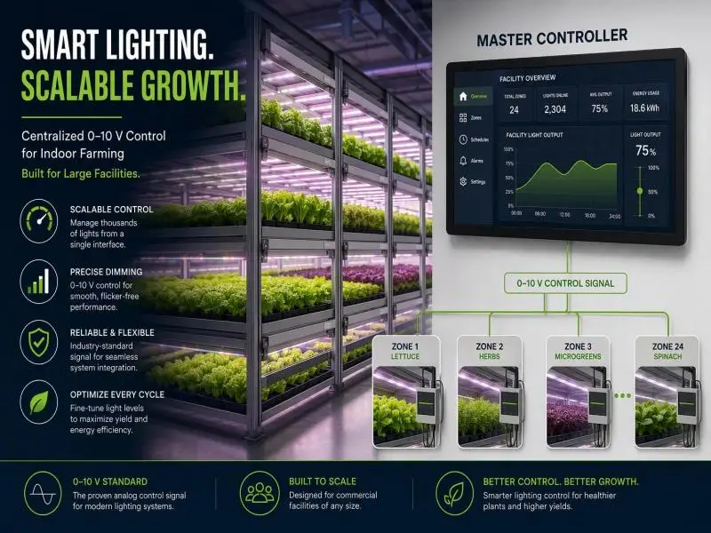
A grow light master controller is the piece of infrastructure that turns a room full of LED fixtures into a single, repeatable light source. In a commercial indoor farm, the difference between a good harvest and a variable one is often not the fixture itself but whether every tier, every rack end, and every corner of the canopy receives the photon flux the crop plan assumed. A master controller sets that level centrally, holds it against a schedule, and gives operations a single place to see what the room is actually doing.
The control layer matters for three reasons. First, uniformity: fixtures at the end of a run and fixtures beside a walkway see different conditions, and a controller with per-zone channels lets you trim zones independently rather than accepting the average. Second, repeatability: a documented dimming level tied to a schedule is reproducible across cycles and across sites, which is what makes a crop plan transferable. Third, energy: dimming is the cheapest kilowatt-hour a cultivation facility will ever find, because it reduces lighting load and the heat that HVAC must remove at the same time.
0–10 V analog dimming is the most widely deployed low-voltage control interface in commercial lighting, and it is well suited to horticultural rooms because it is simple, robust, and supported by a large installed base of drivers. A master controller supplies or sinks a control voltage on a two-wire bus to each driver; the driver reads that voltage and sets output accordingly. Grouping drivers onto controller channels by zone, tier, or crop lets one command move an entire block of fixtures together.
This article covers the fundamentals of the interface and its source/sink behavior, then moves to design and commissioning at scale: channel loading, topology, cabling and noise, off-state switching, and the sensor and scheduling layer that connects control to PPFD and DLI targets. It closes with operations, ROI, and fail-safes, including how lighting control coordinates with HVAC and dehumidification, and what to standardize when you are buying across multiple facilities.
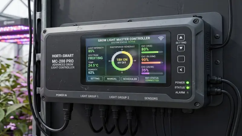
Table of Contents
0–10 V Control Fundamentals
Interface and Dimming Behavior
A 0–10 V dimmable LED driver requires four input conductors: two for line power that energize the driver’s internal processor, and two for the low-voltage control signal that sets output intensity. In North American practice, the control pair is typically violet and pink. The driver maintains maximum output at or above 10 V on the control pair, and minimum output at or below 1 V. On/off switching is not part of the analog signal; it is controlled by switching line voltage to the driver.
That last point drives most of the design decisions that follow. The analog interface dims but does not reliably extinguish. If a driver is fed constant line power, a 0 V command will take it to its minimum level, which may be 1%, 5% or 10% of maximum depending on the driver label — not zero. The minimum light level printed on a driver refers to measured light output relative to maximum, and it may not correspond to power draw or to the control level in any simple way. For a cultivation space, a fixture that sits at 5% output during the dark period is a photoperiod problem, not just an energy problem.
Dimming response is not guaranteed to be linear. Some drivers produce a linear relationship between control voltage and light output; others follow a curve that puts disproportionately more illumination at the low end. Because drivers differ, a functional mock-up of the proposed fixture and controller combination is worth building before committing a room to it.
Two fixtures from different production lots, or with different drivers, can respond differently to the same command — a point the U.S. Department of Energy made concrete in a 2023 test of 23 streetlights, where the range of relative power draw across tested control voltages averaged about 53 percentage points, and 9 of the 19 drivers evaluated for compliance with the ANSI C137.1-2022 voluntary standard were found noncompliant. Horticultural drivers are not streetlight drivers, but the underlying lesson transfers: verify response per driver model rather than assuming the datasheet curve.
Source vs Sink and Polarity
0–10 V drivers use one of two protocols, and mixing them up is the most common commissioning failure in analog dimming.
In sink control — the predominant protocol in commercial lighting, defined in ANSI/NEMA C137.1 and Annex E of IEC 60929 — the driver supplies the control voltage and the controller absorbs (sinks) current to pull the bus down to the desired level. The driver measures the voltage on the control line and sets output accordingly. If the control lines are left open, the driver outputs maximum. If they are shorted, the voltage drops below 1 V, and the driver goes to minimum. All ETC 0–10 V control products, for example, use sink control.
In source control, the controller supplies the voltage, and the driver reads it. Source control is uncommon outside specialist applications, but it exists, and a source-protocol driver on a sink-protocol controller (or the reverse) will not dim as expected — often it will sit at full output or at minimum regardless of command.
Polarity matters within either protocol. The violet conductor is the positive control signal and the pink conductor is signal common. Reversed polarity on a parallel run is a classic cause of the symptom where some fixtures dim and others do not, or where nothing dims at all. Before energizing a zone, confirm the protocol of every driver model on the channel and confirm polarity at each termination, not just at the controller.
Safety and Code Compliance
Analog control wiring may be installed as Class 1 or Class 2, and the choice has consequences for the whole circuit. Class 1 wiring has no voltage or current limits and is treated much like a mains connection; it typically requires conduit, and when control conductors share a conduit with line-voltage conductors, their insulation must be rated for line voltage. Class 2 wiring is power-limited and must be kept separate from Class 1 and line-voltage conductors per NEC 725.136 — the separation is required because line voltage can induce AC voltages on the low-voltage control wiring and produce unpredictable behavior in the fixtures.
The practical rule is that the entire control circuit must be treated consistently. If any part of it — driver, controller, or wire — is designed for a Class 2 installation, keep the whole circuit separate from Class 1 line voltage. Do not run line voltage and low-voltage control wiring in the same conduit, and maintain separation in raceways. Controllers built for Class 2 wiring methods are not interchangeable with Class 1 drivers.
There is a second safety layer inside the driver. Capacitive coupling between the mains side and the control side allows a small amount of line voltage to appear on the 0–10 V control lines. As long as the current is very low, there is no shock hazard, but UL 8750 Supplement SF caps total leakage current on a control circuit at 3.5 mA. Because parallel drivers on one control circuit accumulate leakage, UL 8750 SF8.5 requires the equipment instructions to include the manufacturer’s recommendation for keeping cumulative leakage below that limit.
In practice, few driver manufacturers publish the figure, which makes it difficult for specifiers to know how many drivers can share a circuit before the limit is approached. Where the information is unavailable, treat the channel count as something to confirm with the driver manufacturer rather than assume.
On the product side, the fixture and driver must carry the certifications your authority having jurisdiction (AHJ) will inspect for. In the U.S., that means a mark from an OSHA-recognized Nationally Recognized Testing Laboratory (NRTL) such as UL or ETL, applied within the scope of the applicable standard. In Canada, a Canadian designation is required — cUL, cETL, or CSA — and a plain UL or ETL mark is not Canadian approval on its own. For European deployment, the Low Voltage Directive 2014/35/EU and the CE marking regime govern electrical safety, alongside EMC and RoHS obligations. Confirm the mark, its scope and the issuing site before the submittal goes to the inspector.
Design and Commissioning at Scale
Illustrative channel current budget using the ETC per-driver sink current range (10 µA–2 mA, typically 0.5 mA). The 100 mA channel rating is an example, not a product specification; the UL 8750 Supplement SF 3.5 mA cumulative leakage limit is a separate constraint that parallel drivers also accumulate against.
Channel Loading and Topology
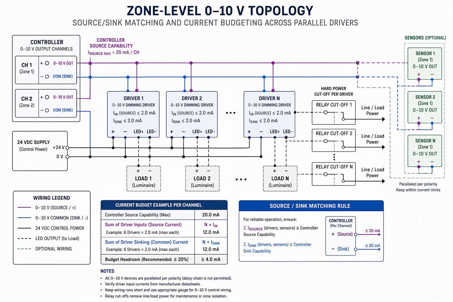
The controller channel is a current budget, and the budget is set by the drivers, not the fixtures. A typical driver draws around 0.5 mA of control current, with a specified range of roughly 10 µA to 2 mA per driver. A controller channel rated to sink 100 mA could, on paper, support 50 drivers at 2 mA each or thousands at 10 µA. Real installations should not be designed to the arithmetic limit.
Best practice is to cap a channel at about 30 drivers, which includes the length of the analog control loop and the number of physical terminations. Note the operative word: drivers, not fixtures. Some luminaires contain multiple drivers, so a channel that looks like it holds 30 fixtures may actually be carrying 60 or more drivers. Count drivers on the bill of materials before you assign channels.
Topology follows the same logic. Parallel connection of drivers on a single control bus is standard, but each additional termination is a potential polarity error, a potential loose connection, and a potential source of leakage accumulation. Zones should be laid out so that a channel maps to a controllable block — a tier, a rack row, a propagation area — and so that the last driver on the run is reachable for service. Keep a channel schedule that records which drivers sit on which channel, their protocol, their minimum level, and their measured response at a few test voltages. That schedule is the document you will use for every future retrofit.
Cabling, Noise, and Off-State Relays
Analog control wiring behaves like an antenna when it is unshielded. Radiated emissions from transformers, motors, and radio equipment can be collected by the control pair and interpreted by the driver as a change in control voltage, which shows up as flicker. Use shielded pair wiring with the shield grounded to earth at the controller. The pair does not need to be twisted, but shielding is strongly recommended where low-end dimming performance matters.
Distance is a design constraint. Best practice limits the analog control run from the controller to the last driver to 300 ft on 18 AWG wire. Extending to 400 ft with 16 AWG is possible but should be treated as an exception, not a default. Long runs also increase the chance of ghost voltages — readings on a high-impedance meter that appear abnormally high because of capacitive coupling from nearby line-voltage conductors. If a measurement looks wrong on a high-impedance meter, repeat it on a low-Z setting before concluding the circuit is faulty.
Off-state design deserves its own line item. Because the 0–10 V signal does not reliably extinguish a driver, the standard practice is to interpose a relay that opens line voltage to the driver when the control signal descends through a low-end cutoff point and closes as it ascends back through it. The relay opening point must be coordinated with the dimmer so it does not open too high in the dimming range (visible step) or too low (fixtures never fully off).
Expect the transition to black to be abrupt. Also expect drivers with onboard processors and firmware to boot and calibrate when line voltage is applied, which can make the first seconds of a lights-on event erratic. For photoperiod-sensitive crops, the relay is the component that guarantees the dark period is actually dark.
Sensors, PPFD/DLI, and Scheduling
A master controller without feedback is an open-loop timer. With a quantum sensor and a schedule, it becomes a closed-loop system that can hold a target rather than a command.
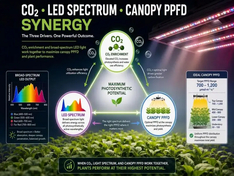
PPFD (photosynthetic photon flux density) is the instantaneous photon flux at the canopy, measured in µmol·m⁻²·s⁻¹. DLI (daily light integral) is the accumulated photons over a photoperiod, in mol·m⁻²·d⁻¹. The conversion is straightforward: DLI equals PPFD multiplied by the photoperiod in seconds, divided by one million.
A calibrated quantum sensor is the instrument that connects the two, and every commercial operation should own at least one. Resource Innovation Institute’s lighting best-practice guide recommends measuring average PPFD across the canopy after installation and using dimming controls to reach target PPFD through the growth cycle.
Commissioning should establish a sensor map, not a single reading. Measure at multiple points across each tier and each zone, at full power and at the dimming levels you intend to run, and record the results. The map tells you which zones need trimming to reach uniformity and which fixtures are underperforming. It also becomes the baseline for tracking flux depreciation: RII notes that growers may consider replacing fixtures after 6–10% depreciation, a change the eye cannot detect, and the DLC’s Q90 lifetime value of 36,000 hours is the qualification basis for listed fixtures.
Scheduling then ties the sensor data to the crop plan. A controller should support at least a photoperiod schedule, dimming setpoints per period, and a DLI target that the controller can chase by adjusting PPFD. Research on adaptive LED control has shown meaningful electricity savings from DLI-targeted dimming — one study reported 20–92% electricity cost reduction by adjusting PPFD thresholds against instantaneous sunlight — but the same body of work cautions that fluctuating DLI can reduce growth in sensitive crops. The controller’s job is to hold the target steadily, not to chase every cloud.
Zone Topology and Current Budgeting
A zone-level topology is easiest to specify as a single drawing. The controller sits at the top with a set of analog output channels. Each channel runs as a shielded pair to a junction point, then in parallel to each driver in the zone. Line voltage reaches each driver through a relay or contactor controlled by the same channel, so that the off command is a line-voltage event rather than a 0 V command.
Sensors — quantum, temperature, humidity — report back to the controller on a separate bus. The drawing should show, for each channel, the driver count, the protocol, the cable length to the last driver, and the relay assignment. That single sheet is what the commissioning agent tests against and what the next retrofit is designed from.
Operations, ROI, and Fail-Safes
Fallback Behaviors and Alerts
The value of a master controller is most visible when something fails. Define the fallback behavior for each failure mode before the room is commissioned, and write it into the sequence of operations.
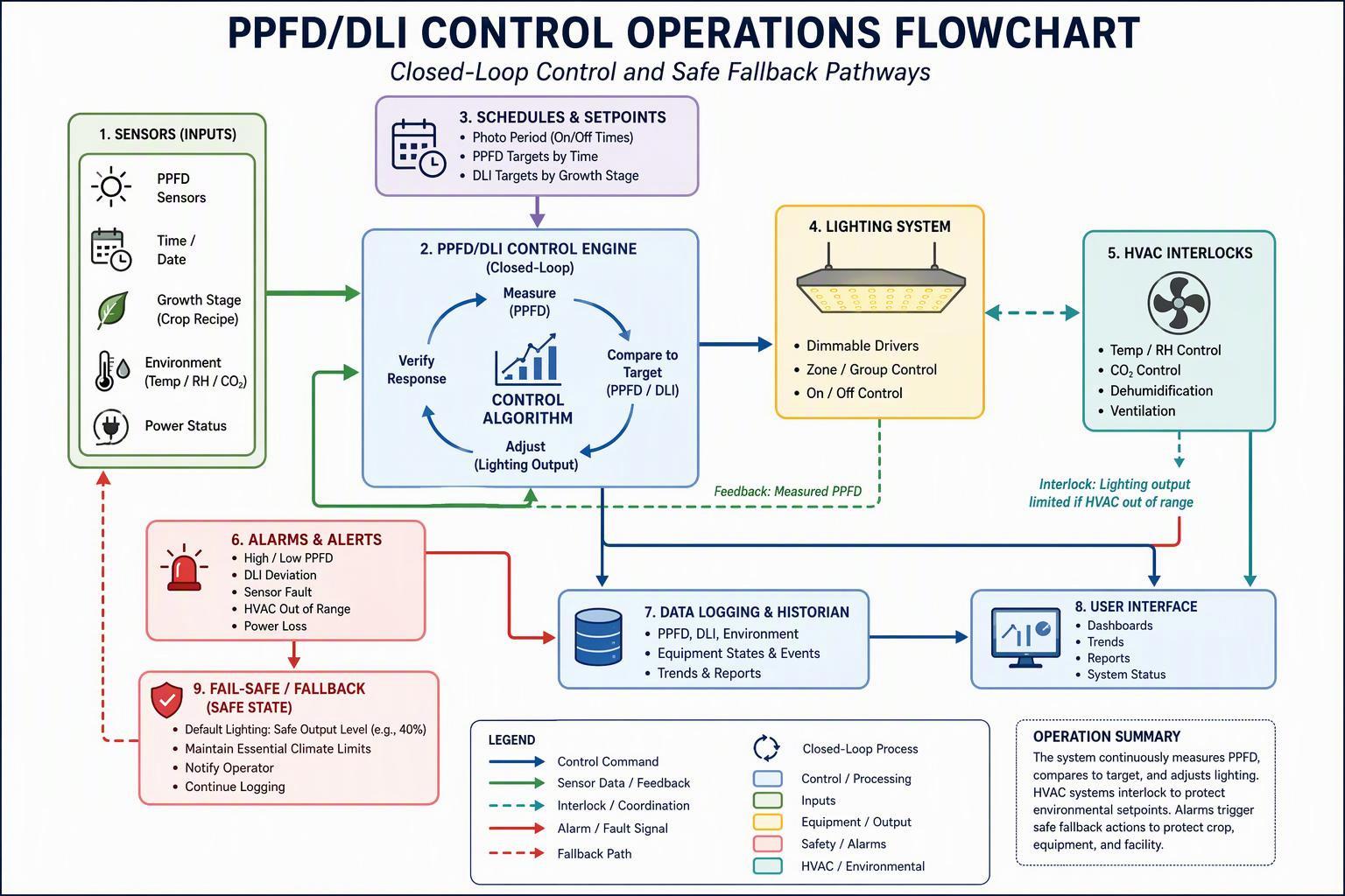
If the controller loses communication with a zone, the drivers will hold whatever control voltage is on the bus. Depending on the driver, that may be full output, minimum output or the last commanded level. Decide which of those is acceptable for each crop stage and specify drivers or relay logic accordingly. If a sensor fails, the controller should fall back to the last known good reading or to the scheduled setpoint, and raise an alarm rather than silently holding a stale value. If a relay fails closed, the zone will not extinguish — a photoperiod risk that should trigger an immediate alert.
Alerts should be tiered. A fixture-level fault is a maintenance ticket; a zone-level loss of control is an operations call; a failure that affects the dark period is an escalation to the head of cultivation. Log every command, every sensor reading, and every alarm with a timestamp. The log is how you reconstruct what happened after a yield deviation, and it is the evidence you need when a driver or fixture is replaced under warranty.
HVAC/Dehumidification Coordination
Lighting and HVAC are one system in an indoor farm, and the controller is where they meet. LED fixtures emit less radiant heat than the HID systems they replace, which changes the sensible load in the room. RII’s HVAC guide notes that indoor facilities retrofitted to LED may need to be air conditioned less than rooms using HID lights, while greenhouses switched to LED may need additional heating capacity. If the lighting schedule changes, the HVAC load profile changes with it.
The coordination point is the schedule. When lights come on, the room gains heat and the plants begin transpiring; when lights go off, the latent load does not disappear. Vapor pressure deficit (VPD) is the practical control variable — RII describes a target of about 1.0 kPa for most food and floriculture crops, with an acceptable range of 0.8–1.2 kPa.
A lighting controller that shares its schedule with the HVAC controller lets the HVAC system pre-stage cooling before lights-on and manage dehumidification through the dark period, when standalone dehumidifiers can run without fighting the cooling system. California’s draft 2028 Title 24 CASE report for controlled environment horticulture makes the same point from the code side: supplemental dehumidification is permitted where it is automated to operate when the primary system cannot meet the load, and integrated HVAC and dehumidification systems remain more efficient than decoupled ones.
Dimming also reduces the heat the HVAC must remove. Every kilowatt-hour not consumed by the fixtures is a kilowatt-hour not rejected into the room, which is why dimming strategies pay twice.
Procurement and Standardization
Procurement is where multi-site operations either gain leverage or lose it. The goal is a standard fixture-and-control package that can be replicated across facilities without re-engineering each room.
Start with the driver. Confirm the protocol (sink or source), the control current draw, the minimum light level, the dimming curve, and the leakage figure, and require the manufacturer to state them in writing. Confirm the certifications your AHJ will inspect: an NRTL mark in the U.S., a Canadian designation for Canadian sites, and CE marking with the applicable directives for European deployment. Confirm that the fixture’s control interface is compatible with the master controller you have standardized on, and test one fixture-and-controller pair before the purchase order is issued.
SLTMAKS is one supplier whose product line is built around these requirements. The company states that its commercial LED grow lights carry ETL, CE, and RoHS certification, use Samsung diodes in a full-spectrum configuration, and support 0–10 V dimming with daisy-chain integration across fixtures. For a multi-site operator, that combination — a documented certification set, a known diode supplier, and a control interface that matches the master controller — is the kind of specification that reduces the number of variables in a standardization program.
The company also maintains warehouses in New York, California, and Oklahoma in the U.S., as well as in Canada and Germany, which shortens the lead time on replacement fixtures and spares. Verify the specific model’s certification scope and control specifications against your own submittal requirements before standardizing.
Standardize the template, not just the hardware. A multi-site lighting template should include the channel schedule, the zone map, the sensor map, the sequence of operations, the fallback matrix, and the commissioning test script. When the template is fixed, a new facility becomes a configuration exercise rather than a design project, and the operating data from one site becomes comparable to the next.
Closed-Loop Control and Fallback Pathways
The operating sequence is easiest to read as a flow. The schedule sets a target DLI for the photoperiod. The controller converts that to a PPFD setpoint and commands the zone channels. The quantum sensor reports actual PPFD; the controller trims the channel to close the gap. The HVAC controller receives the same schedule and pre-stages cooling and dehumidification. If a sensor or channel fails, the controller falls back to the last good setpoint, raises a tiered alarm, and logs the event. The relay opens line voltage at the end of the photoperiod, guaranteeing the dark period. Every step writes to the log, so the room’s light history is reconstructable after the fact.
Conclusion
A grow light master controller is a small piece of hardware with an outsized effect on whether a commercial cultivation facility delivers the same result twice. The design decisions that determine whether it works are mostly made before commissioning: matching the driver protocol to the controller, budgeting control current per channel by counting drivers rather than fixtures, and designing the off state as a line-voltage event rather than trusting a 0 V command.
The operating decisions matter just as much. PPFD and DLI targets belong in the commissioning document, not in a grower’s memory. A sensor map measured at full power and at the dimming levels you actually run gives you the baseline for uniformity and for tracking depreciation. A schedule that the HVAC and dehumidification systems can see turns lighting from an isolated load into part of a coordinated environmental strategy.
For the next facility, the sequence is straightforward. Verify the driver inputs — protocol, current draw, minimum level, dimming curve, and leakage — in writing before the purchase order. Plan the sensor map and the zone map together, so that every controllable block has a measurement point. Define the schedules and the fallback matrix before commissioning, and test the fallbacks as part of the commissioning script. Then standardize the whole package — hardware, channel schedule, sequence of operations, and test script — as a template that can be replicated across sites. The operators who get consistent results are the ones who treated the control layer as engineering, not as an accessory.
FAQ
Why don’t 0-10V LED grow lights turn completely off at 0V?
The 0-10V analog interface is designed for dimming, but it does not reliably extinguish the driver. A 0V command only reduces the light to its minimum level, which could be 1%, 5%, or 10% of its maximum output. To completely shut off the lights and ensure a true dark period, you must use an interposed relay to switch off the line voltage.
What is the difference between sink and source control in 0-10V dimming?
In sink control, the LED driver supplies the control voltage, and the master controller absorbs current to reduce the bus to the desired level. In source control, the controller supplies the voltage for the driver to read. Mixing a source-protocol driver with a sink-protocol controller will prevent the lights from dimming as expected.
How many LED drivers can a master controller channel support?
Best practice caps a single controller channel at about 30 drivers. This practical limit accounts for the analog control loop length, the number of physical terminations, and cumulative leakage current. You must count the actual number of drivers rather than fixtures, because some luminaires contain multiple internal drivers.