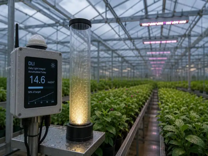
A rain gauge does not tell you whether it is raining right now. It tells you how much water fell since morning. The daily light integral (DLI) works the same way: it is the accumulated photosynthetic light a crop received over a day, not the intensity at any one moment. On a cloudy afternoon, an instantaneous PPFD reading taken between cloud banks can look perfectly adequate while the day’s total quietly falls short of what the crop needs. That gap is the reason DLI-based lighting control exists, and it is also the reason a DLI sensor greenhouse installation is judged on its accumulated data rather than on any single reading.
This article walks through how a DLI control loop measures light, decides on a dimming command, and verifies that the decision was carried out. It also covers the placement, setpoint, and commissioning choices that determine whether the loop works in practice. The caveat belongs up front: a California field demonstration of a vendor-installed DLI system found the technology promising but unproven in commercial settings, because commissioning and operational failures prevented the lights from ever being controlled by sunlight. Verification is therefore treated here as a first-class step, not a closing formality.
Table of Contents
Why a Cloudy Day Breaks Instantaneous Control
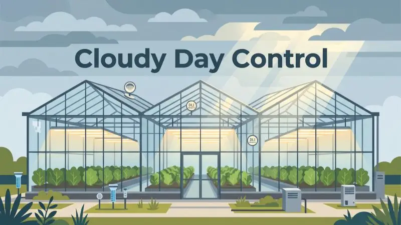
PPFD, measured in µmol·m⁻²·s⁻¹, describes the photon flux striking a square meter every second. DLI, measured in mol·m⁻²·d⁻¹, integrates that flux across the photoperiod. Purdue extension material draws the distinction plainly: instantaneous readings are a snapshot, cumulative readings reflect what the plant actually received, and DLI cannot be determined from an instantaneous reading.
Worked example, not measured data. Assumes a 12-hour photoperiod and 50% greenhouse transmission (Rutgers notes 30% loss for newer houses, 50%+ for older ones). DLI = average canopy PPFD × 0.0864 (Lopez, Purdue/e-GRO). The 10–12 mol·m⁻²·d⁻¹ line is Lopez’s general greenhouse minimum, not a crop-specific setpoint; the supplemental PPFD shown is the arithmetic needed to close the gap over 12 hours.
The arithmetic is not difficult. Take hourly average PPFD values across 24 hours, sum them, and divide by 24 to get a daily average intensity. Purdue’s worked example sums to 3,243 µmol·m⁻²·s⁻¹, divides to an average of 135 µmol·m⁻²·s⁻¹, and multiplies by 0.0864 — the number of seconds in a day divided by one million — to arrive at 11.7 mol·m⁻²·d⁻¹. That single number is the day’s light dose.
A passing cloud illustrates the problem with snapshot control. The sensor reads low for a few minutes, a threshold-based controller switches the fixtures on, the cloud passes, and the fixtures switch off again. Nothing in that sequence establishes whether the day’s total was short. The reverse case is more insidious: a bright morning can carry the instantaneous reading well above any threshold while an overcast afternoon erodes the accumulated total below target, and a controller watching only the current reading never notices. Natural light changes continuously, so no single measurement represents the day.
The consequence is that two controllers facing the same cloudy afternoon can issue opposite commands. One responds to the current PPFD and may do nothing because the sky looks bright enough at that instant. The other compares accumulated DLI against the crop target and dims up because the day is behind. Only the second is answering the question the crop poses.
The Control Loop, Step by Step
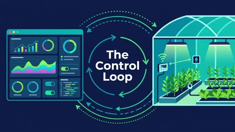
The loop runs in five stages, and each one depends on the previous stage being trustworthy.
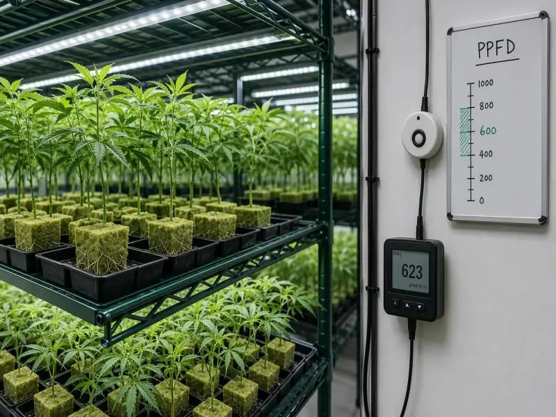
1. Sample. A PAR quantum sensor mounted at canopy height records instantaneous PPFD at a defined interval. Purdue suggests once every 15 to 60 seconds. The sensor feeds a controller, data logger, or environmental control computer.
2. Integrate. The controller accumulates those samples into a running DLI figure for the current photoperiod. This is the step that converts a stream of snapshots into the quantity the crop responds to.
3. Compare. Accumulated DLI is checked against the crop-specific target. The shortfall — target minus delivered — is the input to the next stage.
4. Translate. The shortfall becomes a dimming command. The Title 24 stakeholder proposal for the 2028 code cycle documents one algorithm: determine daylight at the canopy, compare it with the crop-specific threshold, translate the light shortfall into a dimming command, and calculate fixture output and power hourly.
5. Act. The decision branches are explicit. No shortfall means the lights turn off. If the required output falls below the driver’s minimum of 10%, the fixture holds at 10%. Between 10% and 99%, it dims proportionally. Demand above full power caps at full power.
The 10% floor has a practical consequence worth understanding before specifying equipment. A small residual shortfall late in the day does not switch the fixtures off; it runs them at minimum output. Whether that is desirable depends on the driver’s actual minimum dim level and on how the crop responds to low-intensity supplemental light. It also means the loop’s behavior near target is governed by a hardware characteristic, not by the control logic alone.
DLI control differs from the simpler alternative in the same proposal. Option 1 pairs a time clock with a PAR sensor and dims in response to instantaneous PPFD. Option 2 adjusts lighting based on cumulative PPFD measured over the daily photoperiod to meet, but not exceed, a user-defined DLI target. The first responds to the sky at this moment; the second responds to the day so far. Both are proposed compliance pathways for greenhouses above 40 kW of connected horticultural lighting load in California’s 2028 cycle — a proposal under development, not a universal standard.
Setting the Target, Deadband, and Response Delay
The target is the first tunable, and published ranges give a starting point. Virginia Cooperative Extension lists recommended ranges including seedlings at 5–10, lettuce at 12–17, and tomato at 20–30 mol·m⁻²·d⁻¹. Those values are references, not prescriptions. The same guidance states directly that the “correct” DLI is somewhat subjective and not a fixed value, and that because managing DLI involves added cost, the economics of adjusting light levels matter as much as the target itself. A target set without reference to the cost of the electricity and fixtures needed to reach it is an incomplete specification.
Recommended DLI ranges from Virginia Cooperative Extension SPES-720, Table 3. These are general references for common crop types, not stage-specific setpoints and not adjusted for cloudy-day shortfalls; the same guidance states the “correct” DLI is somewhat subjective and that the economics of reaching it matter as much as the target.
Cycling is the second tunable. Michigan State University extension guidance recommends configuring control computers so lights turn on only when ambient light stays below a minimum value for a specific period — the example given is at least 15 minutes below 300 µmol·m⁻²·s⁻¹ — to avoid equipment cycling. That is a response-delay recommendation expressed in instantaneous units, and it addresses a real problem: a threshold without a dwell time will chase passing clouds.
Fixture technology changes the rationale for a deadband. One commercial source states that LED lifespan is not affected by on/off cycling, so LEDs can be controlled with a single setpoint, while HPS fixtures need a deadband to limit cycling and extend bulb life. Treat that as a vendor-stated operational claim rather than an established standard; it is plausible and consistent with how LED drivers work, but it is not a code requirement or a research finding.
Even where a single setpoint is acceptable, a response delay still matters for stable control, because the goal is to avoid chasing short-term fluctuations regardless of what the fixtures can tolerate.
What no retrieved source supplies is a deadband expressed in mol·m⁻²·d⁻¹ for DLI control. The deadband and delay are commissioning choices: set them, document them, and revisit them if the logs show the loop oscillating or lagging.
Mounting, Leveling, and Maintaining a DLI Sensor Greenhouse Installation
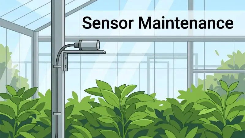
The loop is only as good as its input, and the input depends on physical installation. Purdue’s DLI measurement guidance is specific: place sensors at plant height and adjust the height as the crop grows; use a level to confirm the sensor is level; keep the sensor clear of dust and debris by periodically washing with distilled water and a tissue; and, if possible, return sensors to the manufacturer every few years for recalibration.
Each item addresses a failure mode that produces plausible-looking but wrong data — a sensor left at bench height after the canopy rises reads light the crop never receives, and a tilted sensor reads low because the cosine response falls off with angle.
One sensor is rarely enough. Rutgers extension material shows two sensors at different locations inside a greenhouse over 12 hours, noting that they are for the most part not shaded by the structure at the same time, so their averaged reading better approximates the overall light environment. That is the argument for averaging across a zone rather than trusting a single point. The retrieved sources do not specify a sensors-per-zone count; the number should follow canopy area, the structure’s shading pattern, and the controller’s input capacity, and should be confirmed with the controls vendor.
Calibration range is the subtler trap, and the California field study documents it. The PPFD sensors driving the DLI controls were calibrated for the planned daylight-extension operation and were not calibrated for the low-light conditions of nighttime interruption. When the site switched strategies, the lights operated below the sensors’ calibration range, reducing accuracy. The lesson generalizes: a sensor calibrated for one operating regime may not be accurate in another, so the calibration range must match how the greenhouse actually runs — not how the project plan said it would.
Where DLI Control Collides With Curtains, Photoperiod, and CO2
A DLI loop does not operate in isolation, and three interactions determine whether it helps or fights the rest of the greenhouse.
Shade curtains. A closing curtain reduces canopy light, which the DLI loop reads as a shortfall and may answer with more electric light. Left uncoordinated, the two systems can work against each other — shading to control temperature while lighting to recover the light the shade removed. Purdue lists pulling shade cloth among the decisions informed by instantaneous readings, which is precisely the kind of decision that needs a shared sequence with the lighting logic rather than two independent controllers each pursuing its own setpoint.
Photoperiod. DLI control adjusts intensity within an operating window; the window itself is a photoperiod decision. The California study’s central failure was exactly this boundary being crossed. The site implemented a nighttime interruption strategy timed to crop delivery rather than a daylight extension strategy aimed at a DLI target, and the grower operated the new lights on a fixed nightly schedule instead of modulating output in response to daylight.
The sensors had been selected and calibrated for the daylight-extension case, and the demand-savings case depended on lighting coinciding with peak grid hours that nighttime operation avoided. DLI control cannot repair a photoperiod decision made for other reasons; it can only operate inside the window it is given.
CO2. Rutgers notes research indicating that within certain limits it is possible to reduce the daily light integral requirement while increasing carbon dioxide concentration for the same overall production, and that computer control software is needed to help decide when to add CO2, at what concentration, and when to run supplemental lighting. A DLI target set without reference to the CO2 strategy may therefore be over-lighting — paying for photons that elevated CO2 would have made unnecessary. None of these interactions comes with a required sequence in the sources; they are coordination problems to be resolved in the control narrative.
Verifying the Loop After Commissioning
No universal published procedure exists for accepting a DLI control installation. The closest document is the proposed Title 24 acceptance test protocol, which is a code-compliance proposal rather than an industry standard. It proposes a portable light sensor, a test at the design DLI setpoint, and confirmation that illuminance drops when the setpoint is reduced to 50% of design — with the measured value showing a 50% reduction from the design-setpoint test, stable output with no visible flicker, and only luminaires in the control zone affected by that zone’s setpoint.
The PAR-sensor pathway gets a parallel set of tests at full output, no daylight, full daylight, 95% daylight, and 20–95% daylight, including a zone-isolation check.
The operator’s own verification can be simpler and more informative. Log accumulated DLI against the target daily across a representative cloudy week and a sunny week. Compare delivered DLI to target rather than to fixture runtime — runtime tells you the lights were on, not that the crop received its dose. And confirm the loop is actually in control rather than running on a manual schedule, which is harder to establish than it sounds.
The California demonstration shows why. “Commissioning complete” should mean the full control loop is verified and operational: controller, feedback sensors, and dimming all functioning on solar input. In that project, commissioning delays — including sensor misplacement, circuit protection trips, and a short-circuit in the DC daisy-chain wiring — shortened the fully commissioned period to five days in mid-March, at the end of the supplemental lighting season.
The lights were never controlled based on the amount of sunlight received. During those five days, lighting energy use dropped 26% relative to baseline, but the reduction came from manual shortening of lighting schedules, not from DLI control. A runtime-based check would have credited the control system with a saving it did not produce.
What to Ask a Lighting and Sensor Vendor
The technical content converts cleanly into questions for a lighting and sensor vendor. Ask whether the fixtures accept the dimming signal the controller outputs and what the driver’s minimum dim level is, because the 10% floor governs how the loop behaves near target. Ask how the sensor is calibrated, over what PPFD range, and whether recalibration is available — and whether that range covers the light levels at which the greenhouse will actually operate.
Ask how many sensors the controller supports per zone and how zones are assigned. Ask what the controller logs and whether it exposes accumulated DLI history, since verification depends on that record. Ask what happens on sensor fault or dropout, and what commissioning support is included in the scope.
Where SLTMAKS is relevant to those questions, the supplied first-party facts are these: fixtures are available with 0–10V dimming integration and daisy-chaining, the product line carries ETL, CE, and RoHS certification, there is a 3-year comprehensive product warranty, and finished lights ship from warehouses in North America and Europe. Those are integration and logistics facts — useful when matching fixtures to a controller and planning delivery — not a performance rating and not a claim about DLI control capability. The control logic, sensor calibration, and commissioning quality remain the specifying engineer’s responsibility regardless of which fixtures are selected.
Conclusion
The loop, in one pass: measure accumulated DLI at canopy height, compare it to a crop-specific target, translate the shortfall into a dimming command, and verify against logged data rather than assumed operation. The measurement premise is the one that makes the rest work — DLI is a rain gauge, not a snapshot, and a cloudy day is exactly when the difference between the two matters most.
The sources document two failure modes. The first is a sensor that is mis-mounted, unlevel, dirty, or calibrated for the wrong light range; each produces data that looks reasonable and is not. The second is commissioning that stops before the full loop is proven — the California project reached the end of its supplemental lighting season with the lights never once controlled by sunlight, and the five-day “commissioned” window produced a saving attributable to manual scheduling.
A practical next step: before committing the season’s setpoints, run a one-week logged comparison of delivered DLI against target on the cloudiest stretch available. If the shortfall is being closed and the logs show the loop in control, the setpoints have earned their place. If not, the week has told you which of the two failure modes you are looking at.
FAQ
How is DLI different from a PPFD reading on a cloudy day?
PPFD is an instantaneous rate in µmol·m⁻²·s⁻¹; DLI is the integral of that rate over the day in mol·m⁻²·d⁻¹. DLI cannot be determined from an instantaneous reading. The conversion uses a factor of 0.0864 applied to the daily average PPFD — for example, 135 µmol·m⁻²·s⁻¹ × 0.0864 = 11.7 mol·m⁻²·d⁻¹. On a cloudy day, the instantaneous reading can look adequate while the accumulated total falls short, which is why a snapshot-based controller and a DLI-based controller can make opposite decisions on the same afternoon.
How often should the sensor sample to calculate DLI reliably?
Purdue suggests a defined interval such as once every 15 to 60 seconds, with the controller or data logger integrating those samples into DLI. The interval matters less than the integration: accuracy comes from accumulating samples across the photoperiod and from the sensor being correctly placed, level, clean, and calibrated for the light range in use. A fast sample rate from a mis-mounted sensor still produces a wrong number.
Do I need a deadband if I’m running LEDs instead of HPS?
One commercial source states that LED lifespan is not affected by on/off cycling, so LEDs can be controlled with a single setpoint, while HPS fixtures need a deadband to limit cycling and extend bulb life. Treat that as a vendor-stated operational claim. Even with LEDs, a response delay still matters for stable control — MSU guidance recommends lights turn on only after ambient light stays below a threshold for a defined period, such as at least 15 minutes below 300 µmol·m⁻²·s⁻¹, to avoid chasing passing clouds.
Can I use DLI control if my greenhouse also runs shade curtains?
Yes, but the two systems need a shared sequence. A closing curtain reduces canopy light, which the DLI loop reads as a shortfall and may answer with more electric light. Extension guidance lists pulling shade cloth among decisions informed by instantaneous readings, so the curtain logic and the lighting logic should be coordinated rather than left to pursue independent setpoints.
How do I know the system is actually hitting target and not over-lighting?
Log accumulated DLI against target daily across a cloudy week and a sunny week, and compare delivered DLI to target rather than to fixture runtime. The proposed Title 24 acceptance protocol offers a functional check: lower the DLI setpoint and confirm output drops accordingly, with only the fixtures in that zone responding. And apply the field-study lesson — “commissioned” should mean the full loop is verified, with controller, sensors, and dimming all responding to solar input, because in that project a 26% energy reduction during the five-day commissioning window came from manual scheduling, not DLI control.