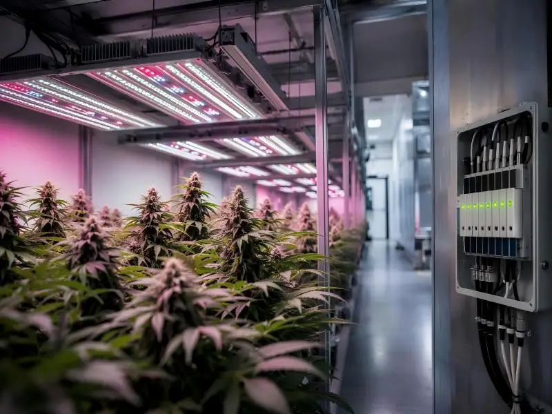
A failed LED driver rarely announces itself as a surge problem. It shows up as flicker, a dimmed row, or a channel that drops out mid-cycle, and by then the damage is already inside the fixture. That pattern matters more in a commercial grow room than almost anywhere else, because every hour of lost light is lost production, and because the electrical environment in these facilities is unusually hostile to sensitive electronics.
This guide covers the essentials of grow room surge protection from the ground up: where surges actually originate, what the codes require, how to design a layered defense, how to select and install the right devices, and what the ongoing inspection and payback picture looks like for a multi-room operation.
Introduction to Grow Room Surge Protection
A driver that fails after a storm is rarely a one-off. It is usually the visible end of a slow process that started months earlier, and it takes a lighting zone, sometimes a whole room, out of production while you wait on replacements. That is the problem this guide addresses: not whether surges are real, but how they shorten fixture life and interrupt cultivation schedules in commercial facilities.
The stakes are concrete. Industrial-grade linear drivers are typically rated 6 kV/3 kA, with 10 kV/5 kA preferred near heavy equipment or in lightning-prone regions, and the higher tier carries roughly a $25 per fixture premium that vendors claim is recovered within a month of avoided downtime (Hi-Hyperlite driver guide, 2026-01-19). A 2025 federal technical bulletin explains the mechanism behind those numbers: metal oxide varistors inside drivers are sacrificial, and repeated surge energy raises leakage current, weakens clamping, and can end in rectifier, capacitor, or switching-device failure (NIH ORF technical bulletin on electrical disturbances and LED drivers, August 2025).
This guide walks through compliant design, device selection, installation practice, and maintenance cadence for multi-room and multi-site operations running 120/208 V, 277 V, and 480/277 V systems. By the end you will be able to specify surge protection for commercial grow rooms that holds up to inspection and to the next storm season.
Table of Contents
Risk Context
That slow, cumulative damage starts with events most operators never see on a utility report. A surge is a brief, high-energy rise in voltage on a circuit; a transient is the same event measured over microseconds, and a surge protective device (SPD) is the component that diverts that energy to ground before it reaches your lighting. Most operators assume the threat arrives from the utility. In grow rooms, the more frequent sources sit inside the building.
Where Surges Come From
Switching events dominate. Contactors and relays opening and closing on a large lighting branch, capacitor bank switching on the utility side, and motors starting on irrigation or HVAC equipment all produce inductive kicks that travel back through the panel. Lightning is the dramatic case, not the common one, and an inland facility with no storm exposure still sees daily transient activity from its own load cycling.
Key Takeaway: Most damaging surge events in a commercial grow room originate inside the facility, from switching and load cycling, not from the utility grid or from lightning.
How Surges Impact LED Drivers
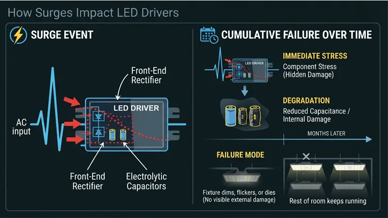
LED drivers are switching power supplies, and their input stage is the most exposed part of the fixture. A transient that exceeds the driver’s input tolerance stresses the front-end rectifier and the electrolytic capacitors behind it. The failure is often cumulative rather than instant: a driver that survives a strike may lose capacitance over the following months and drop out of regulation. That is why LED grow light surge protection is a driver-lifecycle decision, not just a storm-day one. The practical failure mode is a fixture that dims, flickers, or dies with no visible damage, while the rest of the room keeps running at reduced output.
Risk Factors in Grow Facilities
Facility layout and load profile set your exposure. Long feeder runs from a service entrance to a remote grow room, high-density lighting on shared branch circuits, and frequent on/off cycling from lighting schedules all raise the number and severity of transients reaching the drivers. IEEE C62.41.2 classifies these locations as Category A, B and C, based on position relative to the service entrance, and the categories are organized around the 100 kHz ring wave and combination wave standard waveforms. A panelboard feeding a grow room sits in Category B; the branch circuit at the fixture is Category A. Each location sees a different waveform, which is why a single device at the service entrance does not cover the whole facility.
Codes & Standards
Because each location sees a different waveform, the device you install has to satisfy three separate documents. Three documents decide whether the SPD you install survives an inspection and whether it actually protects anything: UL 1449 for the device itself, NFPA 70 Article 242 for how it must be installed, and NFPA 70 Article 250 for the grounding path that makes it work. Each answers a different question, and an inspector will check all three.
UL 1449 Essentials
UL 1449 is the standard that defines what an SPD is and what its label must say. The fourth edition treats Type location, MCOV, VPR, SCCR and In as rating and marking items, and those five terms are the ones worth learning before you compare products.
MCOV is the maximum continuous operating voltage, the highest steady voltage the device tolerates without conducting. VPR, also called clamping or let-through voltage, is the rounded-up measured limiting voltage determined under UL’s 6 kV/3 kA combination-wave test. SCCR is the short-circuit current rating, the available fault current the assembly can withstand as protected. In is the 8/20 µs peak current the device survives while remaining functional after 15 impulses, with UL-assigned values of 3, 5, 10 and 20 kA.
Type location matters just as much. As Intertek’s UL 1449 summary describes it, a Type 1 SPD is permanently connected and installed between the secondary of the service transformer and the line side of the service equipment overcurrent device, and it is also permitted on the load side. Type 1 units include meter-socket enclosures and molded-case SPDs without external overcurrent protection.
NEC Article 242 and 250 Basics
Article 242 governs installation. Per NFPA 70 Article 242, an SPD must be a listed device, and it must be marked with an SCCR and not installed where available fault current exceeds that rating. The marking requirement does not apply to receptacles. Article 242 also consolidates the older Article 280 and Article 285 material, and Article 242’s split at 1000 V nominal separates Part II devices at or below that level from Part III surge arresters above it.
Article 250 is the part operators skip, and it is the reason some SPDs underperform. It requires grounding and bonding to provide an effective ground-fault current path so overcurrent devices operate as intended. The earth itself is not the fault-current path. A surge device bonded to a poor equipment grounding conductor has nowhere useful to send the energy it diverts.
⚠️ Warning: Never install an SPD where the available fault current exceeds its marked SCCR. The device can fail violently under a fault it was never rated to interrupt, and the installation will not pass inspection.
IEEE/IEC Surge Environment
UL and the NEC tell you what to buy and how to mount it. IEEE and IEC describe what the device will actually face: surge current waveforms, expected event frequency, and the energy levels used to classify environments. That distinction matters when you compare an In rating against the surge environment at a specific site, because a rating is a test result, not a prediction of what your service entrance will see.
Layered Design
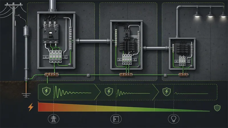
Knowing what the device will face is only half the job; the other half is making sure the stages share the energy instead of one stage absorbing all of it. No single device protects a grow room. Surge energy has to be intercepted in stages, from the service entrance down to the branch circuit feeding each LED driver, and the stages have to be coordinated so they share the work instead of fighting over it.
System Architecture by Voltage
The starting point is a side-by-side Type 1, 2 and 3 comparison that maps each device class to a waveform and a current rating. Type 1 devices are tested with the 10/350 µs lightning current waveform at Iimp values of 12.5 to 50 kA. Type 2 devices are tested with the 8/20 µs waveform at In values of 5 to 20 kA. Type 3 devices are point-of-use units and cannot be used standalone; they always depend on an upstream Type 2.
That hierarchy translates directly into physical placement, and where each SPD type belongs in the distribution hierarchy is well established. A Type 1 device sits at the service entrance or main distribution board, where it can divert direct lightning current. A Type 2 device belongs at every distribution board, which vendor guidance treats as the non-negotiable baseline. A Type 3 device is an add-on at the point of use for sensitive equipment.
For a commercial grow, that means Type 1 and Type 2 SPD coordination at the service and panel level, then Type 3 protection at or near the driver. Skipping the middle layer is the most common architectural mistake.
Grounding and Lead Length
Lead length matters because it changes how much voltage the device can actually clamp. The familiar 10-meter rule is widely repeated as a hard requirement, but why the familiar 10-meter rule is really an energy-coordination requirement is more useful than the number itself. IEC 61643-12 clause 7.2.7 requires energy coordination between stages; the 10-meter figure appears only in informative Annex F, derived from roughly 1 µH per meter of cable. Over 10 meters, that inductance produces an L·di/dt voltage drop large enough to force the upstream device to conduct first. A 10–20 µH decoupling inductor achieves the same sequencing at shorter distances.
Grounding follows the same logic: short, low-impedance bonding conductors from the SPD to the panel ground bar, with no unnecessary bends or loops.
Coordination With Lightning Protection
Coordination is where two-stage designs quietly fall short. A coordinated Type 1 and Type 2 pair can still deliver 1.0 to 1.5 kV to the equipment it protects, according to the same coordination guidance. Electronics rated for a 0.8 kV withstand need a Type 3 SPD within a few meters of the load to close that gap. If the facility has an external lightning protection system, the SPD stages must also be bonded to it so lightning current and surge current share a defined path to ground rather than finding one through the lighting circuits.
Pro Tip: Verify coordination using the SPD manufacturer’s published energy-coordination data rather than assuming a fixed cable distance is sufficient. Distance alone does not guarantee that the upstream device will conduct first.
Selection & Installation
With the architecture fixed, the next decisions are about ratings and workmanship. SPD ratings are not interchangeable, and the first decision is the surge environment the device has to survive. LED Light Expert’s application guide maps how the 4 kV, 6 kV and 10 kV tiers map to applications: 4 kV suits residential and low-risk indoor circuits, 6 kV is the ANSI industrial baseline for high-bay, warehouse and factory LED lighting, and 10 kV covers outdoor or lightning-prone locations. A commercial grow room with long feeder runs and rooftop exposure sits closer to the industrial end than the residential one.
Picking the Right SPD Ratings
The second decision is what the driver’s own surge rating actually covers. A datasheet figure describes the driver’s immunity under a defined test waveform, not a guarantee against every event on the branch. Hi-Hyperlite’s driver guide works through the arithmetic: internal MOSFET and IC drain-source breakdown typically falls between 500 V and 700 V, and if a degraded MOV lets through roughly 800 V, the transistor fails in nanoseconds, before the MOV can dissipate the energy. Professional designs keep clamping voltage at least 15% below the semiconductor breakdown limit and add overvoltage shutdown as a second layer.
For surge protective device selection for LED drivers, that means matching MCOV to the system voltage, checking the kA rating per mode rather than a single combined number, and confirming the clamping voltage leaves headroom under the driver’s internal limit. Engineers should read the per-mode figures; procurement should confirm the listing and warranty terms; operations should note the replacement indicator, because a spent SPD looks identical to a working one.
Panel Placement and Wiring
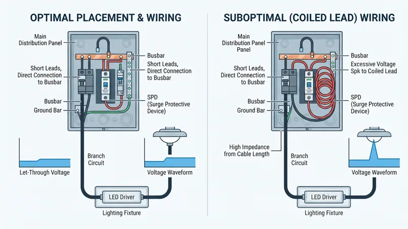
Placement decides how much of the surge reaches the driver. An SPD installed at the panel protects the branch, but the conductor run between panel and fixture adds impedance that lets voltage rise again at the load. Shorter leads and a direct connection to the busbar keep let-through voltage closer to the device’s rated clamping level, which is why a long, coiled lead can quietly undo a well-specified SPD.
SLTMAKS publishes technical guidance on LED driver surge immunity and compliance that can be used to cross-check whether a driver’s stated immunity aligns with the SPD rating selected upstream. Treat it as one reference among several, alongside the driver datasheet and the SPD listing.
Commissioning and Documentation
Commissioning is where the design either holds or quietly fails. Verify the SPD is on the correct side of the disconnect, confirm the ground conductor is bonded to the same reference as the lighting circuit, and record the measured lead length rather than the intended one.
Document four things per panel: SPD model and per-mode kA rating, MCOV, installation date, and the status indicator’s baseline appearance. That record turns a future failure into a diagnostic question instead of a guess, and it gives multi-site teams a comparable baseline when a driver fails after a storm.
ROI & O&M Playbook
That baseline is also what makes the financial case, because surge protection is usually cheaper than the equipment it defends. The published price bands make that gap easy to see. According to LSP’s surge protection device price guide, indicative device price bands run roughly $100 to $900 or more for a Type 1 unit, $30 to $300 for a Type 2 unit, and $5 to $60 for a Type 3 unit, with brand, feature set, and sales channel driving most of the spread. That same guide frames the overall market as “$8 to $800” per device, which is a useful reminder that two quotes for the same job can differ by an order of magnitude before installation labor is counted.
Cost Ranges and Payback
For procurement, the practical takeaway is that the device is rarely the dominant line item in a grow-room electrical budget. Conduit, mounting, labor, and the electrician’s time to land conductors at the correct lead length usually outweigh the SPD itself. Treat the price bands as a planning input, not a quote: get two or three bids on the same specification so you are comparing like scope, not like sticker price.
Payback is harder to state honestly than cost. A single failed driver can cost more than the SPD protecting its branch, but the frequency of that event depends on your local lightning density, feeder length, and utility exposure, so no universal payback period holds across facilities. What you can measure is your own baseline: count driver replacements and lighting downtime events per year before installation, then track the same numbers afterward. That comparison is the only payback figure worth presenting to a capital committee.
Inspection and Monitoring Cadence
SPDs degrade quietly. Metal oxide varistors absorb repeated surges and lose capacity with each event, so a device that still shows a green status light may already be near the end of its useful life. Most units include a visual indicator or a dry contact for remote signaling; wire the contact into your building management system if you have one, because nobody walks a 40-foot ceiling to read a status window.
Set a cadence that matches your risk. A monthly visual check during normal maintenance rounds, a full inspection before and after storm season, and an immediate inspection after any nearby lightning strike covers most commercial operations. Log every check with the date, the indicator state, and the technician’s initials. When a device reaches end of life, replace the cartridge or the unit rather than resetting the indicator.
Multi-Site Standardization
Standardization is where surge protection for commercial grow rooms stops being a per-building decision and becomes an operating standard. Write one specification that fixes the SPD type by location, the voltage and configuration, the surge current rating per mode, and the maximum lead length, then apply it to every new build and retrofit. Sites that let each facility manager choose independently end up with mismatched ratings, inconsistent inspection records, and no way to compare failure data across the portfolio.
Keep the specification short enough that a contractor can bid from it without clarification. Record the installed model, serial number, and commissioning date in your asset register, and review the standard annually against your own failure data.
Conclusion
Surge protection for commercial grow rooms comes down to a chain, not a single device: layered SPDs at the service entrance and the branch panel, ratings matched to the actual surge environment, and installation tight enough that lead length and grounding do not undo the protection you paid for. Get those three right and the results become predictable rather than lucky.
Where to start is a sequence, not a purchase. Standardize the SPD specification across every site so procurement is comparing the same ratings. Build the bill of materials per facility type, including the breaker and conductor sizes the SPD needs. Train the maintenance staff to recognize a spent cartridge, a discolored indicator, or a tripped SPD disconnect. Then put recurring audits on the calendar instead of waiting for a driver to fail.
If you want a second set of eyes on the specification before it goes out to bid, review the SLTMAKS surge protection documentation alongside your electrical contractor’s recommendations.
FAQ
How often should SPDs be inspected or replaced in a commercial grow room?
Split the answer into routine checks and eventual replacement. A monthly visual pass during normal maintenance rounds, a full inspection before and after storm season, and an immediate check after any nearby strike is a common commercial baseline; industry maintenance guides, such as LSP’s SPD maintenance and testing guide, put routine visual checks at quarterly intervals with annual electrical testing for commercial buildings. Replacement is condition-based rather than calendar-based. Under the mixed load and constant switching typical of a grow facility, plan on reviewing devices every five to eight years, and treat a dropped status indicator, rising leakage current, discoloration, or a tripped disconnect as an immediate replacement trigger regardless of age.
What surge current rating should a commercial grow room’s protection carry?
Match the rating to the location rather than picking one number for the whole facility. A Type 2 panel device rated 6 kV/3 kA is a reasonable floor for low-exposure indoor circuits, while 10 kV/10 kA suits long feeder runs, heavy equipment, and any site in a lightning-prone region. Grow rooms tend to sit at the harsher end of that range because dense lighting branches cycle on and off constantly. When you read a spec sheet, check the kA figure per mode rather than a single combined number, since a lumped value can mask weak protection on the neutral-to-ground path.
Do grow lights need Type 1, Type 2 and Type 3 SPDs together?
Yes, and the three perform different jobs. A Type 1 device at the service entrance diverts large lightning and utility-switching energy, Type 2 devices at each distribution board handle the residual let-through, and a Type 3 unit near the fixture closes the last gap that upstream stages cannot. Type 3 devices cannot be installed on their own; they always depend on an upstream Type 2. Skipping the middle layer, or relying on a single service-entrance device, is the most common reason a grow room still loses drivers after a storm.
Conclusion